VT82C686B
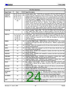
ISA Bus Interface
Signal Name
SA[19:16],
Pin #
K1, K2, P3, P4, IO
P5, R1, R2, R3, IO SA[19-17] are also connected to LA[19-17] of the ISA bus. If the audio interface is
I/O Signal Description
. SA[19-16] are connected to ISA bus SA[19-16] directly.
System Address Bus
/
SA[15-0]
SDD[15-0]
R4, R5, T1, T2,
T3, T4, U1, U2,
U3, V1, V2,
W1
disabled (SPKR pin strapped low), SA[15-0] are connected directly to ISA address
bus pins SA[15-0] (the audio interface pins are used for the IDE secondary data bus).
If the audio interface is enabled (SPKR pin strapped high), SA[15-0] are multiplexed
with the IDE Secondary Data Bus. In this case, SA[15-0] may be connected to both
SDD[15-0] and ISA bus SA[15-0]. However, if ISA address bus loading is a
concern, 74F245 transceivers may be used to externally drive ISA address bus pins
SA[15-0]. In this case, these pins would connect directly to the IDE secondary data
bus and to the transceiver “A” pins and the ISA address bus would connect to the
transceiver “B” pins. SOE# would be used to control the transceiver output enables
and the ISA bus MASTER# signal would drive the transceiver direction controls.
J2, J3, J4, J5
IO
: The LA[23:20] address lines are bi-directional.
System “Latched” Address Bus
These address lines allow accesses to physical memory on the ISA bus up to
16Mbytes. LA[19-17] on the ISA bus are connected to SA[19-17] (see notes above).
LA[23:20]
SD[15:0]
P2, P1, N5, N3, IO
N1, M4, M2,
L5, W4, Y4,
SD[15:0] provide the data path for devices residing on the ISA bus.
System Data.
X-Bus data signals XD[7:0] may be derived if needed from SD[7:0] using an
external 74F245-type transceiver (see the XDIR pin description for transceiver
connection details).
V3, W3, Y3,
W2, Y2, Y1
SD7:4 are strap options for keyboard inputs 6:3 (see Function 0 Rx5A)
F2
IO
SBHE# indicates, when asserted, that a byte is being
System Byte High Enable.
SBHE#
transferred on the upper byte (SD[15:8]) of the data bus. SBHE# is negated during
refresh cycles.
D1
C2
U4
V4
A1
B1
H2
IO
IO
IO
IO
O
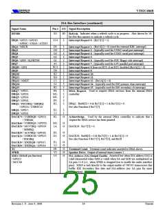
IOR# is the command to an ISA I/O slave device that the slave may drive
data on to the ISA data bus.
IOW# is the command to an ISA I/O slave device that the slave may
latch data from the ISA data bus.
IOR#
I/O Read.
IOW#
I/O Write.
MEMR# is the command to a memory slave that it may drive data
MEMR#
MEMW#
SMEMR#
SMEMW#
BALE
Memory Read.
onto the ISA data bus.
MEMW# is the command to a memory slave that it may latch data
Memory Write.
from the ISA data bus.
SMEMR# is the command to a memory slave, under
Standard Memory Read.
1MB, which indicates that it may drive data onto the ISA data bus
O
SMEMW# is the command to a memory slave, under
Standard Memory Write.
1MB, which indicates that it may latch data from the ISA data bus.
O
BALE is an active high signal asserted by the
Bus Address Latch Enable.
VT82C686B to indicate that the address (SA[19:0], LA[23:17] and the SBHE#
signal) is valid
F3
F1
F4
I
I
I
This signal is driven by I/O devices on the ISA Bus to
indicate that they support 16-bit I/O bus cycles.
ISA slaves that are 16-bit memory devices drive this line
low to indicate they support 16-bit memory bus cycles.
IOCS16#
MCS16#
16-Bit I/O Chip Select.
Memory Chip Select 16.
/
(Rx74[0] = 1). When this signal is asserted, it indicates that a
IOCHCK#
I/O Channel Check
GPI0
parity or an uncorrectable error has occurred for an I/O or memory device on the
ISA Bus. The same pin may optionally be used as General Purpose Input 0.
A2
B2
I
(Rx74[0] = 1). This signal is normally high. Devices on the
I/O Channel Ready
ISA Bus assert IOCHRDY low to indicate that additional time (wait states) is
required to complete the cycle.
IOCHRDY
AEN
O
AEN is asserted during DMA cycles to prevent I/O slaves from
Address Enable.
misinterpreting DMA cycles as valid I/O cycles.
Revision 1.71 June 9, 2000
-18-
Pinouts

 ETC [ ETC ]