VS1005g Datasheet
10 VS1005 PERIPHERALS AND REGISTERS
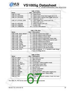
When the DSP has written a packet into the transmit buffer, that is ready to be transmitted
to the PC by an endpoint, the DSP signals the USB firmware by setting the value of the
USB_EP_SENDn register of the endpoint that should transmit the packet (USB_EP_SEND0
for endpoint 0, USB_EP_SEND1 for endpoint 1 etc).
USB_EP_STn Bits
Name
Bits Description
EPnOUT (PC → Device) endpoint (0 .. 3) flags
USB_EP_STn_OTYP
USB_EP_STn_OENA
USB_EP_STn_OSTL
USB_EP_STn_OSTL_SENT
reserved
15:14 00=bulk 01=interrupt 11=isochronous
14:13 1=enabled 0=disabled
12 Force STALL
11 At least 1 STALL sent
10:8 Use ’0’
EPnIN (Device → PC) endpoint (0 .. 3) flags
USB_EP_STn_ITYP
USB_EP_STn_IENA
USB_EP_STn_ISTL
USB_EP_STn_ISTL_SENT
USB_EP_STn_INAKSENT
USB_EP_STn_IXMIT_EMP
reserved
7:6 00=bulk 01=interrupt 11=isochronous
5
4
3
2
1
0
1=enabled 0=disabled
Force STALL
At least 1 STALL sent
At least 1 NAK sent
Transmitter empty
Use ’0’
10.11.2 USB Clocking Modes
USB usage requires a special clock setup. The core clock must be set to 60MHz. If only
Full Speed USB is used the 60MHz clock can be achieved byt placing the PLL to 5x clocking
mode and using 12.000MHz XTAL. When High Speed USB is used the core clock must also be
60MHz but this clock is generated with a PLL which can be programmed with fractional multi-
plier factors. The xtal oscillator frequencies of 12.000MHz or 12.288MHz are recommended in
this mode.
10.11.3 USB Host
USB module can be configured as an USB host. In USB host mode the 1.5kOhm pull up
resistor in D+ pin is replaced with 15kOhm pull down resistors in in both the D+ and D- pins.
USB host is capable of:
• Send Start of Frame (SOF) packets
• Send SETUP, IN and OUT packets
• Schedule transfers within 1ms frames
• Signal USB bus reset
• Provide USB power management
Version: 0.2, 2012-03-16
69

 ETC [ ETC ]