VS1005g Datasheet
9
FIRMWARE OPERATION
9 Firmware Operation
The firmware uses the following pins (see the example schematics in Section 6):
Pin Description
PWRBTN High level starts regulator, is also read as the Power button Key.
GPIO0_0 external 1 MΩ pull-down resistor, Key 1 connects a 100 kΩ pull-up resistor 1
GPIO0_1 external 1 MΩ pull-down resistor, Key 2 connects a 100 kΩ pull-up resistor
GPIO0_2 external 1 MΩ pull-down resistor, Key 3 connects a 100 kΩ pull-up resistor
GPIO0_3 external 1 MΩ pull-down resistor, Key 4 connects a 100 kΩ pull-up resistor
GPIO0_4 external 1 MΩ pull-down resistor, Key 5 connects a 100 kΩ pull-up resistor
GPIO0_6 external pull-down resistor for USB Mass Storage Device, pull-up for USB
Audio Device
GPIO0_7 external pull-down resistor for 1.8 V I/O voltage, pull-up resistor for 3.3 V I/O
voltage
NFCE
external pull-up resistor for normal operation, pull-down to use RAM disk for
UMS Device
XCS
SI
SO
USBN
USBP
external pull-up to enable SPI EEPROM boot
Power LED control during firmware operation
Feature LED control during firmware operation
external 1 MΩ pull-up
external 1 MΩ pull-up
1
Smaller pull-down resistors may be needed for keys if the capacitance on the GPIO pins is
high.
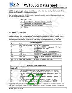
Boot order:
Stage
Description
Power on
Power button (PWRBTN) pressed when VHIGH has enough volt-
age
Reset
Power-on reset, XRESET, or watchdog reset causes software
restart
UART Boot
Almost immediately after power-on UART can be used to enter
emulator mode.
SPI EEPROM Boot
If XCS is high, SPI Boot is tried.
NAND FLASH probed If NFCE is high, NAND FLASH is checked.
Default firmware
The firmware in ROM takes control.
9.1 SPI Boot
The first boot method is SPI EEPROM. If GPIO1_0 is low after reset, SPI boot is skipped. If
GPIO1_0 is high, it is assumed to have a pull-up resistor and SPI boot is tried.
First the first four bytes of the SPI EEPROM are read using 16-bit address. If the bytes are
“VLS5” (for protected host) or “WLS5” (for unprotected host), a 16-bit EEPROM is assumed
and the boot continues. If the last 3 bytes are read as “VLS”, a 24-bit EEPROM is assumed
and boot continues in 24-bit mode. Both 16-bit and 24-bit EEPROM should have the “VLS5” or
Version: 0.2, 2012-03-16
26

 ETC [ ETC ]