VS1005g Datasheet
11 VS1005 DEBUGGER
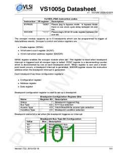
Vs1005 JTAG instruction codes
Instruction IR register Description
BYPASS
“0000” Places jtag to bypass mode. In bypass mode
there is one clock cycle delay between tdi and
tdo.
IDCODE
“1111” Places jtag’s 32-bit ID code register between tdi
and tdo.
The snooper module supports up to 8 breakpoints which can be programmed to trigger at
data/address events. Snooper’s control and status registers are
• Enable register (SENA)
• 16-bit event count register (ECNT)
• 16-bit instruction address register (BADDR)
SENA register enables the snooper module when set. The register is reset when breakpoint
interrupt is triggered and all snooper logic is halted. ECNT register is a decrementing counter
which is decremented by one at each breakpoint event. When register is zero and a break-
point event occurs, a breakpoint interrupt is generated. BADDR register stores the instruction
address when the breakpoint interrupt is generated.
Each breakpoint has three configuration registers:
• Configuration register
• Address register
• Data register
Breakpoint configuration register is used to set-up a breakpoint.
Breakpoint Configuration Register Bits
Name
Register Bit Description
Status
7
Breakpoint triggered flag
Bus Type
6:5 X/Y/I bus selection
Access Type
Condition Type
4:3 Fetch/Read/Write access type selection
2:0 Breakpoint condition selection
Breakpoint status bit is set when the breakpoint triggeres an interrupt.
Breakpoint Bus Type Bit Configuration
Value
Bus Description
’00’
’01’
’10’
’11’
I
X
Y
Breakpoint at I-bus
Breakpoint at X-bus
Breakpoint at Y-bus
Illegal Don’t use
Version: 0.2, 2012-03-16
101

 ETC [ ETC ]