Application Hints (Continued)
e
e
V
V
I
Nominal line voltage AC rms
Low line voltage AC rms
NOM
Input and Output Capacitors
LOW
The LM196 will tolerate a wide range of input and output
capacitance, but long wire runs or small values of output
capacitance can sometimes cause problems. If an output
capacitor is used, it should be 1 mF or larger. We suggest 10
mF solid tantalum if significant improvements in high fre-
quency output impedance are needed (see output imped-
ance graph). This capacitor should be as close to the regu-
lator as possible, with short leads, to reduce the effects of
lead inductance. No input capacitor is needed if the regula-
tor is within 6 inches of the power supply filter capacitor,
using 18 gauge stranded wire. For longer wire runs, the
LM196 input should be bypassed locally with a 4.7 mF (or
larger) solid tantalum capacitor, or a 100 mF (or larger) alu-
minum electrolytic capacitor.
e
DC output current
OUT
e
e
Example: I
10A, V
OUT
5V
OUT
e
e
Assume: V
2.2V, V
1.2V
REG
RECT
e
e
V
V
5
2 Vp-p, V
115V,
RIPPLE
NOM
e
105V
LOW
a
a
a
1.2 1
2.2
115
e
e
V
rms
1.1
2
105
#
0
(5.3 10 ) (I
J # J
8.01 V
rms
b
3
c
)
OUT
e
Capacitor C
c
2
V
RIPPLE
b
3
c
(5.3 10 )(10)
2
e
e
26,500 mF
Correcting for Output Wire Losses (LM196/LM396)
The diodes used in a full-wave rectified capacitor input sup-
ply must have a DC current rating considerably higher than
the average current flowing through them. In a 10A supply,
for instance, the average current through each diode is only
5A, but the diodes should have a rating of 10A–15A. There
are many reasons for this, both thermal and electrical. The
diodes conduct current in pulses about 3.5 ms wide with a
peak value of 5–8 times the average value, and an rms
value 1.5–2.0 times the average value. This results in long
term diode heating roughly equivalent to 10A DC current.
The most demanding condition however, may be the one
cycle surge through the diode during power turn on. The
peak value of the surge is about 10–20 times the DC output
current of the supply, or 100A–200A for a 10A supply. The
diodes must have a one cycle non-repetitive surge rating of
200A or more, and this is usually not found in a diode with
less than 10A average current rating. Keep in mind that
even though the LM196 may be used at current levels be-
low 10A, the diodes may still have to survive shorted output
conditions where average current could rise to 12A–15A.
Smaller transformers and filter capacitors used in lower cur-
rent supplies will reduce surge currents, but unless specific
information is available on worst-case surges, it is best not
to economize on diodes. Stud-mounted devices in a DO-4
package are recommended. Cathode-to-case types may be
bolted directly to the same heat sink as the LM196 because
the case of the regulator is its power input. Part numbers to
consider are the 1N1200 series rated at 12A average cur-
rent in a DO-4 stud package. Additional types include com-
mon cathode duals in a TO-3 package, both standard and
Schottky, and various duals in plastic filled assemblies.
Schottky diodes will improve efficiency, especially in low
voltage applications. In a 5V supply for instance, Schottky
diodes will decrease wasted power by up to 6W, or alterna-
tively provide an additional 5% ‘‘drop out’’ margin for low-
line conditions. Several manufacturers are producing ‘‘high
efficiency’’ diodes with a forward voltage drop nearly as
good as Schottkys at high current levels. These devices do
not have the low breakdown voltages of Schottkys, so are
much less prone to reverse breakdown induced failures.
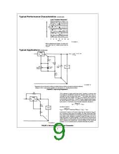
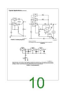
Three-terminal regulators can only provide partial Kelvin
load sensing (see Load Regulation). Full remote sensing
can be added by using an external op amp to cancel the
effect of voltage drops in the unsensed positive output lead.
In Figure 7, the LM301A op amp forces the voltage loss
across the unsensed output lead to appear across R3. The
current through R3 then flows out the Vb pin of the op amp
through R4. The voltage drop across R4 will raise the output
voltage by an amount equal to the line loss, just cancelling
j
the line loss itself. A small ( 40 mV) initial output voltage
error is created by the quiescent current of the op amp.
Cancellation range is limited by the maximum output current
of the op amp, about 300 mV as shown. This can be raised
by increasing R3 or R4 at the expense of more initial output
error.
Transformers and Diodes
Proper transformer ratings are very important in a high cur-
rent supply because of the conflicting requirements of effi-
ciency and tolerance to low-line conditions. A transformer
with a high secondary voltage will waste power and cause
unnecessary heating in the regulator. Too low a secondary
voltage will cause loss of regulation under low-line condi-
tions. The following formulas may be used to calculate the
required secondary voltage and current ratings using a full-
wave center tap:
a
a
a
V
RECT
V
V
V
OUT
REG
RIPPLE
e
V
rms
2
#
0
J
Minimum input-output voltage of regulator
V
NOM
*
(1.1)
V
# J # J
LOW
e
I
(I
) (1.2)
(Full-wave center tap)
rms
where:
OUT
e
e
V
V
V
DC regulated output voltage
OUT
REG
e
Rectifier forward voltage drop at three times DC
output current
RECT
e
V
1/2 peak-to-peak capacitor ripple voltage
b
RIPPLE
3
(5.3 10 ) (I
c
)
OUT
e
2C
*The factor of 1.1 is only an approximate factor accounting for load regula-
tion of the transformer.
6

 ETC [ ETC ]