Typical Performance Characteristics (Continued)
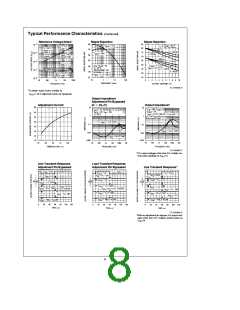
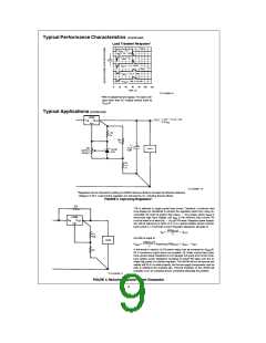
Load Transient Response*
TL/H/9059–9
*With no adjustment pin bypass. For output volt-
ages other than 5V, multiply vertical scale by
V
/5.
OUT
Typical Applications (Continued)
TL/H/9059–10
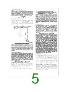
*Regulation can be improved by adding an LM336 reference diode to increase the effective reference
voltage to 3.75V. Load and line regulation are improved by 3:1, including thermal effects.
FIGURE 3. Improving Regulation*
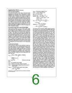
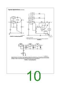
*R3 is selected to supply partial load current. Therefore, a minimum load
must always be maintained to prevent the regulated output from rising un-
b
is the minimum load current. R3
controlled. R3 must be greater than (V
V
)/I
OUT MIN
, where V
is
MAX
MAX
worst-case high input voltage, and I
MIN
2
V ) /R3 watts. Regulator power dissipa-
OUT
b
must be rated for at least (V
IN
tion will be reduced by a factor of 2–3 in a typical situation where minimum
load current is 1/2 full load current. Regulator dissipation will peak at:
(R3)(I
2
)
OUT
e
a
V
IN
V
OUT
MAX
and will be equal to:
2
(R3)(I
)
OUT
s
e
b
V
P
Assuming: (R3)(I
)
V
MAX
OUT
OUT
4
2
) /
A few words of caution; (1) R3 power rating must be increased to (V
MAX
R3 if continuous output shorts are possible. (2) Under normal load condi-
tions, system power dissipation is not changed, but under short circuit condi-
2
tions system power dissipation increases by (V ) /R3 watts over the al-
IN
ready high power of a shorted regulator. The LM196 will not be harmed and
neither will R3 if it is rated properly, but the raw supply components must be
able to withstand the overload also. Thermal shutdown of the LM196 will
probably occur for sustained shorts, somewhat alleviating the problem.
TL/H/9059–11
FIGURE 4. Reducing Regulator Power Dissipation
9

 ETC [ ETC ]