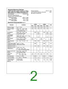
Electrical Characteristics (Note 1) (Continued)
LM196
Typ
LM396
Typ
Parameter
Conditions
Units
Min
Max
Min
Max
s
s
12V
b
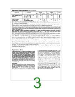
Power Dissipation (P
(Note 11)
)
7.0V
V
V
OUT
70
50
36
100
70
50
36
100
W
W
W
MAX
IN
b
e
e
V
V
V
15V
18V
IN
OUT
OUT
b
V
IN
e
Full Temperature Range
Drop-Out Voltage
LM196/LM396
I
10A,
2.1
2.5
2.1
2.5
V
OUT
2.75
2.75
e
b
e
V
OUT
e
5V, I 10 mA to 10A.
OUT
Note 1: Unless otherwise stated, these specifications apply for T
25 C, V
§
j
IN
Note 2: This is a worst-case specification which includes all effects due to input voltage, output current, temperature, and power dissipation. Maximum power
(P ) is specified under Electrical Characteristics.
MAX
Note 3: Line regulation is measured on a short-pulse, low-duty-cycle basis to maintain constant junction temperature. Changes in output voltage due to thermal
gradients or temperature changes must be taken into account separately. See discussion of Line Regulation under Application Hints.
Note 4: Load regulation on the 2-pin package is determined primarily by the voltage drop along the output pin. Specifications apply for an external Kelvin sense
connnection at a point on the output pin (/4 from the bottom of the package. Testing is done on a short-pulse-width, low-duty-cycle basis to maintain constant
×
junction temperature. Changes in output voltage due to thermal gradients or temperature changes must be taken into account separately. See discussion of Load
Regulation under Application Hints.
Note 5: Ripple rejection is measured with the adjustment pin bypassed with 25 mF capacitor, and is therefore independent of output voltage. With no load or
e
expressed in %/V. At frequencies below 100 Hz, ripple rejection may be limited by thermal effects, if load current is above 1A.
c
V
[
]
where K is line regulation
bypass capacitor, ripple rejection is determined by line regulation and may be calculated from; RR
20 log
100/(K
)
OUT
10
Note 6: Thermal regulation is defined as the change in output voltage during the time period of 0.2 ms to 20 ms after a change in power dissipation in the regulator,
due to either a change in input voltage or output current. See graphs and discussion of thermal effects under Application Hints.
Note 7: Adjustment pin current change is specified for the worst-case combination of input voltage, output current, and power dissipation. Changes due to
temperature must be taken into account separately. See graph of adjustment pin current vs temperature.
Note 8: Current limit is measured 10 ms after a short is applied to the output. DC measurements may differ slightly due to the rapidly changing junction temperature,
tending to drop slightly as temperature increases. A minimum available load current of 10A is guaranteed over the full temperature range as long as power
b
dissipation does not exceed 70W, and V
IN
V
is less than 7.0V.
OUT
Note 9: Minimum load current of 10 mA is normally satisfied by the resistor divider which sets up output voltage.
Note 10: Total thermal resistance, junction-to-ambient, will include junction-to-case thermal resistance plus interface resistance and heat sink resistance. See
discussion of Heat Sinking under Application Hints.
Note 11: Although power dissipation is internally limited, electrical specifications apply only for power dissipation up to the limits shown. Derating with temperature
is a function of both power transistor temperature and control area temperature, which are specified differently. See discussion of Heat Sinking under Application
b
Hints. For V
IN
V
less than 7V, power dissipation is limited by current limit of 10A.
OUT
Note 12: Dropout voltage is input-output voltage differential measured at a forced reference voltage of 1.15V, with a 10A load, and is a measurement of the
minimum input/output differential at full load.
Application Hints
Further improvements in efficiency can be obtained by using
Schottky diodes or high efficiency diodes with lower forward
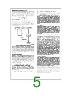
This requires careful attention to all sources of thermal re-
voltage, combined with larger filter capacitors to reduce rip-
is guaranteed to dissipate up to 70W continuously, as long
as the maximum junction temperature limit is not exceeded.
sistance from junction-to-ambient, including junction-to-
ple. However, this reduces the voltage difference between
case resistance, case-to-heat sink interface resistance
input and drive pins and may not allow sufficient voltage to
fully saturate the pass transistor. Special transformers are
available from Signal Transformer that have a 1V tap on the
loy Thermocote must be used when mounting the LM196,
output winding to provide the extra voltage for the drive pin.
(0.1–1.0 C/W), and heat sink resistance itself. A good ther-
§
mal joint compound such as Wakefield type 120 or Thermal-
especially if an electrical insulator is used to isolate the reg-
The transformers are available as standard items for 5V ap-
ulator from the heat sink. Interface resistance without this
plications at 5A, 10A and 20A. Other voltages are available
on special request.
compound will be no better than 0.5 C/W, and probably
§
much worse. With the compound, and no insulator, interface
resistance will be 0.2 C/W or less, assuming 0.005 or less
×
§
Heat Sinking
combined flatness run-out of TO-3 and heat sink. Proper
torquing of the mounting bolts is important to achieve mini-
mum thermal resistance. Four to six inch pounds is recom-
mended. Keep in mind that good electrical, as well as ther-
mal, contact must be made to the case.
Because of its extremely high power dissipation capability,
the major limitation in the load driving capability of the
LM196 is heat sinking. Previous regulators such as LM109,
LM340, LM117, etc., had internal power limiting circuitry
which limited power dissipation to about 30W. The LM196
3

 ETC [ ETC ]