ICL7104
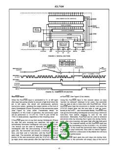
18/16 THREE-STATE OUTPUTS
18/16 LATCHES
HBEN
MBEN
(-16 ONLY)
INITIAL
CLEAR
18/16 BIT COUNTER
LATCH
LBEN
CLOCK
COMP OUT
CE/LD
TO
ANALOG
SECTION
AZ
CONVERSION
CONTROL
LOGIC
OSCILLATOR
AND CLOCK
CIRCUITRY
HANDSHAKE
LOGIC
INT
DEINT(+)
DEINT(-)
2
26
R/H
24
23
25
21
MODE
27
STATUS
CLOCK CLOCK CLOCK
(1) (2) (3)
SEND
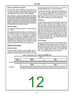
FIGURE 9. DIGITAL SECTION
OPTION -14
-16
MIN
7161 28665
8185 32761
MAX
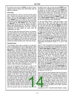
DEINT TERMINATED
AT ZERO CROSSING
DETECTION
STATIC IN
HOLD STATE
INT
PHASE
INTEGRATOR
OUTPUT
7 COUNTS
INTERNAL
CLOCK
INTERNAL
LATCH
STATUS
OUTPUT
RUN/HOLD
INPUT
FIGURE 10. RUN/HOLD OPERATION
at Run/Hold. See Figure 10 for details.
Run/Hold Input
When the Run/Hold input is connected to V+ or left open Using the Run/Hold input in this manner allows an easy
(this input has pullup resistor to ensure a high level when the “convert on demand” interface to be used. The converter
pin is left open), the circuit will continuously perform may be held at idle in Auto-Zero with Run/Hold low. When
conversion cycles, updating the output latches at the end of Run/Hold goes high the conversion is started, and when the
every Deintegrate (Phase III) portion of the conversion cycle STATUS output goes low the new data is valid (or trans-
(See Figure 8). (See under “Handshake Mode” for ferred) to the UART - see Handshake Mode). Run/Hold may
exception.) In this mode of operation, the conversion cycle now go low terminating Deintegrate and ensuring a minimum
will be performed in 131,072 for 7104-16 and 32768 for Auto-Zero time before stopping to wait for the next
7104-14 clock periods, regardless of the resulting value.
conversion. Alternately, Run/Hold can be used to minimize
conversion time by ensuring that it goes low during Deinte-
grate, after zero crossing, and goes high after the hold point
is reached. The required activity on the Run/Hold input can
be provided by connecting it to the CLOCK3 (-14), CLOCK2
(-16) Output. In this mode the conversion time is dependent
on the input value measured. Also refer to Intersil Applica-
tion Bulletin A030 for a discussion of the effects this will have
on Auto-Zero performance.
If Run/Hold goes low at any time during Deintegrate (Phase
III) after the zero crossing has occurred, the circuit will
immediately terminate Deintegrate and jump to Auto-Zero.
This feature can be used to eliminate the time spent in
Deintegrate after the zero-crossing. If Run/Hold stays or
goes low, the converter will ensure a minimum Auto-Zero
time, and then wait in Auto-Zero until the Run/Hold input
goes high. The converter will begin the Integrate (Phase II)
portion of the next conversion (and the STATUS output will If the Run/Hold input goes low and stays low during Auto-
go high) seven clock periods after the high level is detected Zero (Phase I), the converter will simply stop at the end of
13

 ETC [ ETC ]