CD-700, VCXO Based PLL
Loop Filter
A PLL is a feedback system which forces the output frequency to lock in both phase and frequency to the
input frequency. While there will be some phase error, theory states there is no frequency error. The loop
filter design will dictate many key parameters such as jitter reduction, stability, lock range and acquisition
time. Be advised that many textbook equations describing loop dynamics, such as capture range or lockin
time, are based on ideal systems. Such equations may not be accurate for real systems due to
nonlinearities, DC offsets, noise and don’t take into account the limited VCXO bandwidth. This section
deals with some real world design examples. Also, there is loop filter software on the Vectron web site,
plus a full staff of experienced applications engineers are eager to assist in this process. Common CD-
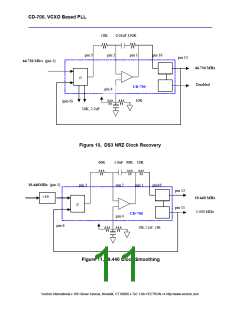
700 PLL applications are shown in Figures 7, 8 (frequency translation), 9 (clock recovery) and 10 (clock
smoothing).
Of primary concern to the designer is selecting a loop filter that insures lock-in, stability and provides
adequete filtering of the input signal. A good starting point for the the loop filter bandwidth is 100ppm times
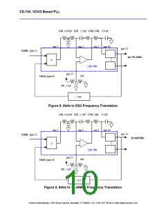
the DATAIN frequency. An example would be translating an 8kHz signal to 44. 736MHz – DS3 – which is
= 100 ppm * 8kHz = 8Hz . So for 8kHz inputs, ~ 8 Hz loop bandwidth may be reasonable and Figures 7
and 8 show and 8kHz to DS3 and 8kHz to 19.440 MHz frequency translation designs.
It’s fairly easy to set a low loop bandwidth for large frequency translations such as 8kHz to 44.736MHz, but
becomes more difficult for clock smoothing applications such as 19.440MHz in and 19.440MHz output. In
this example, 100ppm * 19.440MHz is about 2kHz and may be too high to reject jitter.
A good way to resolve this is to lower the input frequency such as dividing the input frequency down. The
loop filter bandwidth becomes lower since 100ppm * DATAIN is lowered. Figure 10 shows an example of
how to design a low loop bandwith on a relatively high input signal and still maintain a wide lock range.
The “100ppm * DATAIN frequency” loop filter bandwidth can then be tailored to the application, since
lower bandwidthds are desriable to clean up and or translate clock signals and higher bandwidths may be
needed for clock recovery of NRZ signals.
There is no known accurate formula for calculating acquisition time and so the best way to provide realisitc
figures is to measure the lock time for a CD-700. By measuring the control voltage settling time, aquisiton
was measured is in the range of 3-5 seconds for applications such as 8kHz to 34.368 MHz frequency
translation which is similar to the application in Figures 7 and 8, to sub 10 milliseconds for NRZ data
patterns such as figure 9. It may be tempting reduce the damping factor to 0.7 or 1.0 in order to increase
acquisition time; but, it degrades stability and will not signifigantly decrease lock time. This is due to the
fact that most VCXO’s have a 10kHz bandwidth so setting a 100kHz loop bandwidth is impossible. A
damping factor of 4 is fairly conservative and allows for excellent stability.
Some general quidelines for selecting loop filter include: Values should be less than 1Megohm and at
least 10Kohm between the PHO and OPN, the capacitor should be low leakage and a polarized capacitor
is acceptable, the R/C’s should be located physically close to the CD-700 . Aslo, the loop filter software
available on the web site was written for 5 volt operation, a simple way to calculate values for 3.3 volt
operation is to times the data density by 0.66 (3.3V / 5V).
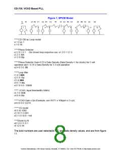
SPICE models are another design aid. In most cases a new PLL CD-700 design is calculated by using the
software and verified with SPICE models, and depending on the circumstances evaluated in the
applications lab. The simple active pi model is in Figure 7.
Loop filter values can be modified to suit the system requirements and application. There are many
excellent references on designing PLL’s, such as “Phase-Locked Loops, Theory, Design and
Applications”, by Roland E Best McGraw-Hill; however, there is loop filter software on the Vectron web
site, plus a staff of experienced applications engineers to assist in this process.
Vectron International • 166 Glover Avenue, Norwalk, CT 06856 • Tel: 1-88-VECTRON-1• http://www.vectron.com

 ETC [ ETC ]