In addition to storing the 1553 message data, the RAM imple-
ments the Stacks and Look-Up Tables required for the different
modes of operation. A global double buffering mechanism is
available to prevent partially updated information from being
transferred to or from the 1553 Bus. For RT mode, there is a pro-
grammable option to separate broadcast message data from
non-broadcast data. This provides compliance to MIL-STD-
1553. In addition, for RT mode, there is the choice of storing
either a single message, a double buffer data structure, or a cir-
cular buffer data structure. The size of the circular buffer is pro-
grammable up to 8192 words, on a Tx/Rx/Bcst-subaddress
basis.
messages processed. In addition to the stack processing, the
memory management logic performs storage, retrieval, and
manipulation functions involving pointer and message data
structures for all three modes.
The BU-65552, BU-65551 and BU-65550 provide a number of
programm-able options for RT mode memory management. In
compliance with MIL-STD-1553, received data from broadcast
messages may be optionally separated from nonbroadcast
received data. For each transmit, receive or broadcast subad-
dress, either a single-message data block or a variable-sized
(128 to 8192 words) circular buffer may be allocated for data
storage. In addition to helping ensure data consistency, the cir-
cular buffer feature provides a means of greatly reducing host
processor overhead for bulk data transfer applications. End-of-
message interrupts may be enabled either globally, following
error messages, on a Tx/Rx/Bcst-subaddress basis, or when any
particular Tx/Rx/Bcst-subaddress circular buffer reaches its
lower boundary.
The BU-65552, BU-65551 and BU-65550 support programma-
ble command illegalization for RT mode. This allows individual
T/R
Command Words to be illegalized as a function of
bit, sub-
address, and word count/mode code. Since the illegalization
scheme is RAM based, it is inherently self-testable.
A Descriptor Stack or Command Stack is maintained for BC, RT,
and MT modes. This records the status of each message, the
time the message was transmitted or received, and contains
either the received 1553 command and Data Block Pointer (in
RT or MT mode) or the actual address of the 1553 message
block (in BC mode). In RT mode, a Lookup Table is provided to
store the addresses of the data blocks to be used when receiv-
ing or transmitting messages for the individual subaddresses.
INTERRUPTS
The BU-65552, BU-65551 and BU-65550 provide many pro-
grammable options for interrupt generation and handling. The
interrupt output pin (
modes of operation: a pulse, a level output cleared under soft-
ware control, or a level output automatically cleared following a
read of the Interrupt Status Register.
INT
) has three software programmable
The PC Cards RT mode is multiprotocol, supporting MIL-STD-
1553A, MIL-STD-1553B Notice 2, STANAG 3838 (including
EFA bus), and the McAir A3818, A5232, and A5690 protocols.
Individual interrupts are enabled by the Interrupt Mask Register.
The host processor may easily determine the cause of the inter-
rupt by using the Interrupt Status Register. The Interrupt Status
Register provides the current state of the interrupt conditions.
The Interrupt Status Register may be updated in two ways. In the
standard interrupt handling mode, a particular bit in the Interrupt
Status Register will be updated only if the condition exists and
the corresponding bit in the Interrupt Mask Register is enabled.
In the enhanced interrupt handling mode, a particular bit in the
Interrupt Status Register will be updated if the condition exists
regardless of the contents of the corresponding Interrupt Mask
Register bit. In any case, the respective Interrupt Mask Register
bit enables an interrupt for a particular condition.
The BU-65552, BU-65551 and BU-65550 implement three mon-
itor modes: a word monitor, a selective message monitor, and a
combined RT/selective message monitor.
PCMCIA INTERFACE
The BU-65552, BU-65551 and BU-65550 provide a Card
Information Structure (CIS) within the attribute memory space of
the PCMCIA interface. The CIS contains device configuration
information structures called basic compatibility tuples. The for-
mat of these configuration tuples is defined within the PCMCIA
interface standard. In addition to the CIS there are the four stan-
dard PCMCIA configuration registers (Configuration Option
Register, Card Configuration and Status Register, Pin
Replacement Register, and Socket and Copy Register).
The BU-65552, BU-65551 and BU-65550 provide maskable
interrupts and 15-bit Interrupt Status Register for end of mes-
sage, end of BC message list, erroneous messages, Status Set
(BC mode), Time Tag Register Rollover, RT Address Parity Error
conditions, BC retry, data stack rollover, command stack
rollover, transmitter watchdog timeout, or RAM parity error. The
Interrupt Status Register allows the host processor to determine
the cause of all interrupts by means of a single READ operation.
The CIS, also referred to as the Metaformat, provides a level of
device information which allows a card resource manager or an
application program to identify and fully configure the card.
INTERNAL COMMAND ILLEGALIZATION
MEMORY MANAGEMENT
The BU-65552, BU-65551 and BU-65550 implemen internal
command illegalization for RT mode. The illegalization architec-
ture allows for any subset of the 4096 possible combinations of
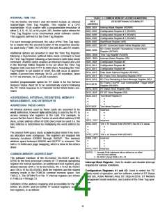
The BU-65552, BU-65551 and BU-65550 incorporate complete
memory management and processor interface logic. The soft-
ware interface to the host processor is implemented by means
of 24 on-board registers plus up to 64K words of RAM. For all
three modes, a stack area of RAM is maintained. In BC mode,
the stack allows for the scheduling of multimessage frames. For
all three modes, the stack provides a real-time chronology of all
T/R
broadcast/own address,
bit, subaddress, and word
count/mode code to be illegalized. The illegalization scheme is
under software control of the host processor. As a result, it is
inherently self-testable.
3

 ETC [ ETC ]