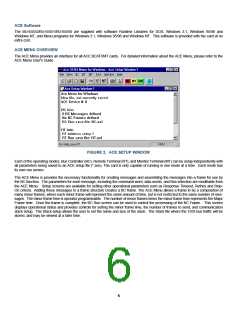
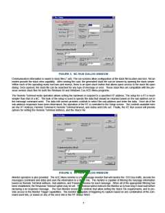
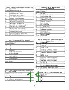
FIGURE 3. BC RUN DIALOG WINDOW
Communication information is saved in stack files (*.asf). The run screens allow configuration of the stack file location and size. All run
modes provide the stack view capability. After running the card, the generated stack file can be viewed by opening the stack viewer.
Within each of the operating mode tool bars and menus, there is an open stack button that allows quick access to the stack file open
dialog. Once opened, the stack file can be searched for any type of message or error. These stack files are compatible with the pre-
vious version stack files for both the Windows 95 and Windows 3.xx ACE Menu programs.
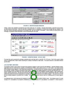
The Remote Terminal mode operation allows setting the hardware to respond to a specified RT address. The setup for a RT is much
simpler than that of a BC. The bulk of the setup is used to specify the data that should be returned based on the sub-address set in
the message command word. The data edit screen provides controls to select the sub-address and enter the data. Once all of the
sub-address responses have been determined, the operation of the RT is controlled in the Setup screen. The controls available here
are the RT Address, Remote Terminal to Remote Terminal timeout, and status word bits set. Finally, the RT Run screen will provide
options for setting the Remote Terminal Address, and the Stack File.
FIGURE 4. RT RUN DIALOG WINDOW
Monitor operation is also provided. The ACE Menu monitor is a full message monitor that will monitor the 1553 bus traffic, decode the
messages (command and data) and save the information to a Stack File. The monitor is capable of filtering the message information
based on Remote Terminal address, Sub-address, and Transmit/Receive for each message. When all of the appropriate filtering has
been established, the Response Timeout option may be set. The timeout option instructs the Monitor as to how long it must wait before
declaring a no response message. The Run Monitor screen has controls that allow setting the Stack File requirements, and to pro-
vide access to the Monitor Trigger capabilities. The monitor is capable of triggering its capture based on any combination of the com-
mand word bits, or based on any of the error bits in the RT Status Word.
7

 ETC [ ETC ]