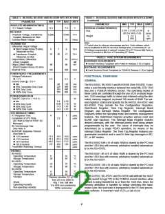
TABLE 1. BU-65552, BU-65551 AND BU-65550 SPECIFICATIONS
TABLE 1. BU-65552, BU-65551 AND BU-65550 SPECIFICATIONS
(continued)
PARAMETER
MIN
TYP
MAX UNITS
PARAMETER
MIN
TYP
MAX UNITS
ABSOLUTE MAXIMUM RATINGS
+5 V Supply Voltage
-0.3
7.0
V
PHYSICAL CHARACTERISTICS
3.370 x 2.126 x 0.197
(85.6 x 54.0 x 5.0)
Size
in
(mm)
oz
RECEIVER
Threshold Voltage, Transformer
Coupled, Measured on Stub
Common Mode Voltage
0.200
0.860
10
VP-P
Weight
2.8
(80)
(gm)
VPEAK
Notes:
TRANSMITTER
(1) Typical value for minimum intermessage gap time. Under software control,
may be lengthened to (65,535 ms minus message time), in increments of 1 µs.
(2) Software programmable (4 options). Includes RT-to-RT Timeout (Mid-Parity of
Transmit Command to Mid-Sync of Transmitting RT Status).
Differential Output Voltage
! Direct Coupled Across 35 ohms,
Measured on Bus
! Transformer Coupled,
Measured on Stub
Output Noise, Differential
(Direct Coupled)
Output Offset Voltage,
Direct Coupled Across 35 ohms
Rise/Fall Time
6
7
9
27
VP-P
VP-P
18
20
TABLE 2. HOST SYSTEM REQUIREMENTS
10
mVP-P,
diff
mV
HARDWARE REQUIREMENTS
! Socket Interface Compliant with PCMCIA Release 2.10 or higher
-90
90
SOFTWARE REQUIREMENTS
! Card Services Driver Compliant to PCMCIA Release 2.10 or higher
100
300
nsec
POWER SUPPLY REQUIREMENTS
Voltages/Tolerances
! + 5 V
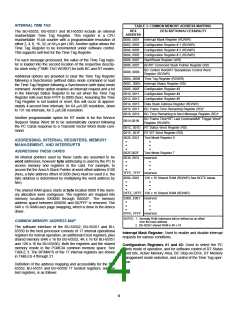
FUNCTIONAL OVERVIEW
4.5
5.5
V
GENERAL
Current Drain @ + 5.0 V
80
110
300
490
860
mA
mA
mA
mA
! Idle
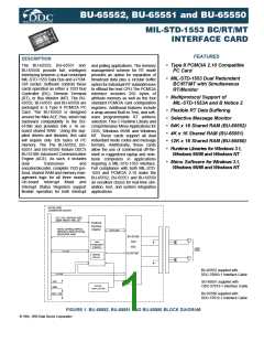
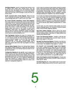
The BU-65552, BU-65551 and BU-65550 (See FIGURE 1) pro-
vides a user-friendly interface between the serial MIL-STD-1553
Bus and a PCMCIA interface socket. The operating modes of
these cards are controlled through the use of 24 on-board regis-
ters. 1553 message traffic is stored and retrieved using the ded-
icated, memory mapped, on-board 12K words of RAM. The var-
ious registers control and operate the BU-65552, BU-65551 and
BU-65550. They include the five Configuration Registers,
Start/Reset Register, Time Tag Register, Interrupt Mask
Register, and Interrupt Status Register. The Configuration
Registers define the operating mode and memory management
features. The Start/Reset Register provides various reset and
BC/MT start functions. The Interrupt Mask Register enables
desired interrupts, with the interrupt priority level being jumper
programmable by the user. The cause of interrupts may be
determined by a single READ operation, by means of the
Interrupt Status Register. The Time Tag Register features pro-
grammable resolution and is used to time tag messages in BC,
RT, or MT modes.
225
385
700
! 25% Transmitter Duty Cycle
! 50% Duty Cycle
! 100% Duty Cycle
POWER DISSIPATION
Total PC Card (Vcc = +5.0 V)
! Idle
W
0.4
0.55
1.18
1.81
3.07
0.98
1.16
1.47
W
W
W
! 25% Duty Cycle
! 50% Duty Cycle
! 100% Duty Cycle
1553 MESSAGE TIMING
RT Response Time
Completion of CPU Write
(BC Start-to Start of FIRST BC
Message)
BC Intermessage Gap
(See Note 1)
BC/RT/MT Response Timeout
(See Note 2)
4
7
µsec
µsec
2.5
9.5
µsec
17.5
21.5
49.5
127
18.5
22.5
50.5
128
668
19.5
23.5
51.5
129
µsec
µsec
µsec
µsec
µsec
! 18.5 nominal
! 22.5 nominal
! 50.5 nominal
! 128.0 nominal
The BU-65552 64K x16 of static RAM is shared by the PC host
and the 1553 Bus with memory arbitration handled automatical-
ly by the BU-65552.
Transmitter Watchdog Timeout
THERMAL
BU-65552
The BU-65551 4K x16 of static RAM is shared by the PC host
and the 1553 Bus with memory arbitration handled automatical-
ly by the BU-65551.
Operating Temperature
Storage Temperature
BU-65551
0
-20
55
65
°C
°C
Operating Temperature
Storage Temperature
BU-65550
Operating Temperature
Storage Temperature
Vibration
-25
-55
70
80
°C
°C
The BU-65550 12K x16 of static RAM is shared by the PC host
and the 1553 Bus with memory arbitration handled automatical-
ly by the BU-65550.
0
-20
55
65
°C
°C
The BU-65552, BU-65551 and BU-65550 will withhold the WAIT
signal (assert to logic "0") to the PCMCIA socket interface while
a word is being transferred to or from the 1553 Bus. Since the
memory arbitration is handled by simply stretching the hand-
shake cycle, the wait state is transparent to the PC host proces-
sor's software. A maximum wait of 2.6 µs can occur
Random vibration, 0.1 g2 / Hz
from 20 Hz to 2000 Hz
40g, 11ms, half sine
0 to 95% non-condensing
100% condensing
Shock
Operating Humidity
Non-operating Humidity
2

 ETC [ ETC ]