THAT 4301 Dynamics Processor IC
Page 9
Applications
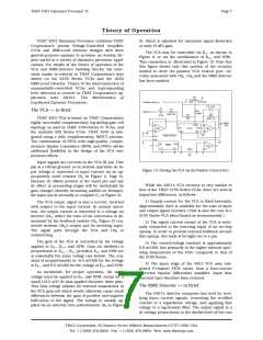
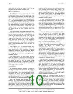
The circuit of Figure 14, Page 9, shows a typical
application for THAT 4301. This simple compres-
sor/limiter design features adjustable hard-knee
threshold, compression ratio, and static gain1. The
applications discussion in this data sheet will center
on this circuit for the purpose of illustrating impor-
tant design issues. However, it is posslble to config-
ure many other types of dynamics processors with
THAT 4301. Hopefully, the following discussion will
imply some of these possibilities.
verting stage. If, for some reason, more than 0 dB
gain is required when the VCA is set to unity, then
the resistors may be skewed to provide it. Note that
the feedback capacitor (C2) is required for stability.
The VCA output has approximately 45 pf of capaci-
tance to ground, which must be neutralized via the
47 pf feedback capacitor across R2.
The VCA gain is controlled via the EC– terminal,
whereby gain will be proportional to the negative of
the voltage at EC–. The EC+ terminal is grounded, and
the SYM terminal is returned nearly to ground via a
small resistor (R3, 51 W). The VCA SYM trim (R5,
50 kW) allows a small voltage to be applied to the
SYM terminal via R4 (300 kW). This voltage adjusts
for small mismatches within the VCA gain cell,
thereby reducing even-order distortion products. To
adjust the trim, apply to the input a middle-level,
middle-frequency signal (1 kHz at 1 V is a good
Signal Path
As mentioned in the section on theory, the VCA
input pin is a virtual ground with negative feedback
provided internally. An input resistor (R1, 20kW) is
required to convert the ac input voltage to a current
within the linear range of the 4301. (Peak VCA input
currents should be kept under 1 mA for best distor-
tion performance.) The coupling capacitor (C1, 47 mf)
is
strongly
recom-
mended to block dc cur-
rent from preceeding
stages (and from offset
voltage at the input of
the VCA). Any dc current
into the VCA will be
modulated by varying
gain in the VCA, showing
up in the output as
“thumps”. Note that C1,
in conjunction with R1,
will set the low fre-
quency limit of the cir-
cuit.
VCA SYM
C1
R1
+15
R5
50K
20K0 1%
47uF
+15
THRESHOLD
-15
R9
R4
300K
CCW
R11
47pF
C2
10K0 1%
R12
10K
R3
51
CR2
CR1
383K 1%
R10
R2
20K0 1%
CW
2M00 1%
R8
-15
OUT
SYM
-
-
4k99 1%
+15
IN
EC-
OUT
EC+
OA1
+
OA3
+
VCA
IN
C7
C8
100n
The VCA output is
connected to OA3, config-
ured as an inverting cur-
rent-to-voltage converter.
OA3‘s feedback compo-
nents (R2, 20 kW, and
C2, 47 pf) determine the
THAT4301
VCC
VEE
100n
+
OA2
-
C3
47uF
IN RMS
IT
OUT
CT
-15
R6
GND
10K0 1%
R16
R7
2M00
1%
4k99 1%
C6
C4
10uF
+15
C5
100N
GAIN
R14
1K43
1%
22uF
constant
of
cur-
CW
COMPRESSION
R13
10K
CW
-15
rent-to-voltage
conver-
R18
10K
R17
sion. The simplest way
to deal with this is to
recognize that when the
VCA is set for unity
(0 dB) gain, the input to
output voltage gain is
simply R2/R1, just as in
the case of a single in-
590K
1%
R15
10K0
CCW
CCW
1%
-15
Figure 14. Typical Compressor/Limiter Application Circuit
1. More information on this compressor design, along with suggestions for converting it to soft-knee operation,
is given in AN100, Basic Compressor Limiter Design. The designs in AN100 are based on THAT Corporation’s
2150-Series VCAs and 2252 RMS Detector, but are readily adaptable to the 4301 with only minor modifications. In
fact, the circuit presented here is functionally identical to the hard-knee circuit published in AN100.
THAT Corporation; 45 Sumner Street; Milford, Massachusetts 01757-1656; USA
Tel: +1 (508) 478-9200; Fax: +1 (508) 478-0990; Web: www.thatcorp.com

 ETC [ ETC ]