THAT 4301 Dynamics Processor IC
Page 7
Theory of Operation
THAT 4301 Dynamics Processor combines THAT
Corporation’s proven Voltage-Controlled Amplifier
(VCA) and RMS-Level Detector designs with three
general-purpose opamps to produce an Analog En-
gine useful in a variety of dynamics processor appli-
cations. For details of the theory of operation of the
VCA and RMS-Detector building blocks, the inter-
ested reader is referred to THAT Corporation’s data
sheets on the 2150 Series VCAs and the 2252
RMS-Level Detector. Theory of the interconnection of
exponentially-controlled VCAs and log-responding
level detectors is covered in THAT Corporation’s ap-
plication note AN101, The Mathematics of
Log-Based Dynamic Processors.
2), which is adjusted for minimum signal distortion
at unity (0 dB) gain.
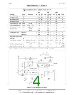
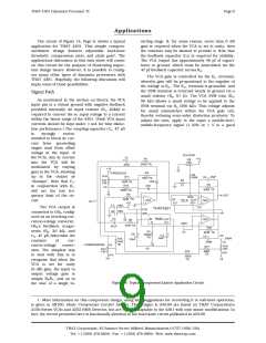
The VCA may be controlled via EC-, as shown in
Figure 2, or via the combination of EC+ and SYM.
This connection is illustrated in Figure 13. Note that
this figure shows only that portion of the circuitry
needed to drive the positive VCA control port; cir-
cuitry associated with OA1, OA2 and the RMS detector
has been omitted.
R5
VCA SYM
50K
Positive Control In
Signal In
C2 47pF
C1
R1
The VCA — in Brief
R4
300K
20K0 1%
R2
R3
51
47uF
THAT 4301 VCA is based on THAT Corporation’s
highly successful complementary log-antilog gain cell
topology, as used in THAT 2150-Series IC VCAs, and
the modular 202 Series VCAs. THAT 4301 is inte-
grated using a fully complementary, BiFET process.
The combination of FETs with high-quality, comple-
mentary bipolar transistors (NPNs and PNPs) allows
additional flexibility in the design of the VCA over
previous efforts.
20K0 1%
Signal
Out
SYM
-
-
IN
EC-
OUT
EC+
OA1
VCA
OA3
+
+
THAT4301
VCC
VEE
+
IN
It
OUT
Ct
RMS
OA2
-
GND
Input signals are currents to the VCA IN pin. This
pin is a virtual ground, so in normal operation an in-
put voltage is converted to input current via an ap-
propriately sized resistor (R1 in Figure 2, Page 4).
Because dc offsets present at the input pin and any
dc offset in preceeding stages will be modulated by
gain changes (thereby becoming audible as thumps),
the input pin is normally ac-coupled (C1 in Figure 2).
Figure 13. Driving the VCA via the Positive Control Port
While the 4301’s VCA circuitry is very similar to
that of the THAT 2150 Series VCAs, there are several
important differences, as follows:
1) Supply current for the VCA is fixed internally.
Approximately 2mA is available for the sum of input
and output signal currents. (This is also the case in a
2150 Series VCA when biased as recommended.)
The VCA output signal is also a current, inverted
with respect to the input current. In normal opera-
tion, the output current is converted to a voltage via
inverter OA3, where the ratio of the conversion is de-
termined by the feedback resistor (R2, Figure 2) con-
nected between OA3‘s output and its inverting input.
The signal path through the VCA and OA3 is
noninverting.
2) The signal current output of the VCA is inter-
nally connected to the inverting input of an on-chip
opamp. In order to provide external feedback around
this opamp, this node is brought out to a pin.
The gain of the VCA is controlled by the voltage
applied to EC–, EC+, and SYM. Gain (in decibels) is
proportional to EC+ – EC-, provided EC+ and SYM are
at essentially the same voltage (see below). The con-
stant of proportionality is –6.5 mV/dB for the voltage
at EC–, and 6.5 mV/dB for the voltage at EC+ and SYM.
3) The control-voltage constant is approximately
6.5 mV/dB, due primarily to the higher internal oper-
ating temperature of the 4301 compared to that of
the 2150 Series.
4) The input stage of the 4301 VCA uses inte-
grated P-channel FETs rather than a bias-current
corrected bipolar differential amplifier. Input bias
currents have therefore been reduced.
As mentioned, for proper operation, the same
voltage must be applied to EC+ and SYM, except for a
small (±2.5 mV) dc bias applied between these pins.
This bias voltage adjusts for internal mismatches in
the VCA gain cell which would otherwise cause small
differences between the gain of positive and negative
half-cycles of the signal. The voltage is usually ap-
plied via an external trim potentiometer (R5 in Figure
The RMS Detector — in Brief
The 4301’s detector computes rms level by recti-
fying input current signals, converting the rectified
current to a logarithmic voltage, and applying that
voltage to a log-domain filter. The output signal is a
dc voltage proportional to the decibel-level of the rms
THAT Corporation; 45 Sumner Street; Milford, Massachusetts 01757-1656; USA
Tel: +1 (508) 478-9200; Fax: +1 (508) 478-0990; Web: www.thatcorp.com

 ETC [ ETC ]