Page 10
Rev. 04/10/02
choice with this circuit) and observe THD at the sig-
nal output. Set the trim for minimum THD.
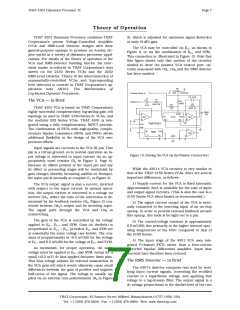
loop such that the junction of R9 and CR2 (the output
of the threshold detector) sits at -(R9/R8) RMSOUT. For
the circuit of Figure 14, this is –2 RMSOUT. Negative
signals from the RMS detector drive the output of
OA1 positive, reverse biasing CR2 and forward biasing
CR1. In this case, the junction of R9 and CR2 rests at
0 V, and no signal level informaion is passed to the
threshold detector’s output.
RMS-Level Detector
The RMS detector’s input is similar to that of the
VCA. An input resistor (R6, 10 kW) converts the ac in-
put voltage to a current within the linear range of the
4301. (Peak detector input currents should be kept
under 1 mA for best linearity.) The coupling capacitor
(C3, 47 mf) is recommended to block dc current from
preceeding stages (and from offset voltage at the in-
put of the detector). Any dc current into the detector
will limit the low-level resolution of the detector, and
will upset the rectifier balance at low levels. Note
that, as with the VCA input circuitry, C3 in conjunc-
tion with R6 will set the lower frequency limit of the
detector.
In order to vary the threshold, R12, the THRESH-
OLD control, is provided. Via R11 (383 kW), R12 adds
up to ±39.2 mA of current to OA1‘s summing junction,
requiring the same amount of opposite-polarity cur-
rent from the RMS detector output to counterbalance
it. At 4.99 kW, the voltage across R8 required to pro-
duce a counterbalancing current is ± 195 mV, which
represents a ±30 dB change in RMS detector input
level.
The time response of the RMS detector is deter-
mined by the capacitor attached to CT (C4, 10 mf) and
the size of the current in pin IT (determined by R7,
2 MW and the negative power supply, –15V). Since the
voltage at IT is approximately 0 V, the circuit of Figure
14 produces 7.5 mA in IT. The current in IT is mir-
rored with a gain of 1.1 to the CT pin, where it is
available to discharge the timing capacitor (C4). The
combination produces a log filter with time constant
equal to approximately 0.026 CT/IT (~35 ms in the
circuit shown).
Since the RMS detector’s 0 dB reference level is
85 mV, the center of the THRESHOLD pot’s range
would be 85 mV, were it not for R10 (2 MW), which
provides an offset. R10 adds an extra –7.5 ma to OA1‘s
summing junction, which would be counterbalanced
by 37.4 mV at the detector output. This corresponds
to 5.8 dB, offsetting the THRESHOLD center by this
much to 165 mV, or approximately -16 dBV.
The output of the threshold detector represents
the signal level above the determined threshold, at a
constant
of
about
13
mV/dB
(from
The waveform at CT will follow the logged (deci-
bel) value of the input signal envelope, plus a dc off-
set of about 1.3 V (2 VBE). This allows a polarized
capacitor to be used for the timing capacitor, usually
[R9/R8] 6.5 mV/dB). This signal is passed on to the
COMPRESSION control (R13), which variably attenu-
ates the signal passed on to OA2. Note that the gain of
OA2, from the wiper of the COMPRESSION control to
OA2‘s output, is R16/R15 (0.5), precisely the inverse of
the gain of OA1. Therefore, the COMPRESSION con-
trol lets the user vary the above-threshold gain be-
tween the RMS detector output and the output of OA1
from zero to a maximum of unity.
an electrolytic. The capacitor used should be
a
low-leakage type in order not to add significantly to
the timing current.
The output stage of the RMS detector serves to
buffer the voltage at CT and remove the 1.3 V dc off-
set, resulting in an output centered around 0 V for in-
put signals of about 85 mV. The output voltage
increases 6.5 mV for every 1 dB increase in input sig-
nal level. This relationship holds over more than a
60 dB range in input currents.
The gain control constant of the VCA, 6.5 mV/dB,
is exactly equal to the output scaling constant of the
RMS detector. Therefore, at maximum COMPRES-
SION, above threshold, every dB increase in input
signal level causes a 6.5 mV increase in the output of
OA2, which in turn causes a 1 dB decrease in the VCA
gain. With this setting, the output will not increase
despite large increases in input level above threshold.
This is infinite compression. For intermediate set-
tings of COMPRESSION, a 1 dB increase in input sig-
nal level will cause less than a 1 dB decrease in gain,
thereby varying the compression ratio.
Control Path
A compressor/limiter is intended to reduce its
gain as signals rise above a threshold. The output of
the RMS detector represents the input signal level
over a wide range of levels, but compression only oc-
curs when the level is above the threshold. OA1 is
configured as a variable threshold detector to block
envelope information for low-level signals, passing
only information for signals above threshold.
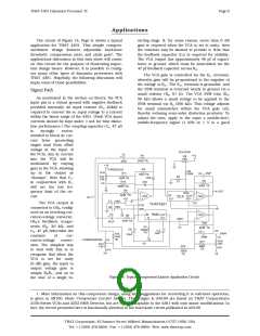
The resistor R14 is included to alter the taper of
the COMPRESSION pot to better suit common use. If
a linear taper pot is used for R13, the compression ra-
tio will be 1:2 at the middle of the rotation. However,
1:2 compression in an above-threshold compressor
is not very strong processing, so 1:4 is often pre-
ferred at the midpoint. R14 warps the taper of R13 so
that 1:4 compression occurs at approximately the
midpoint of R13‘s rotation.
OA1 is an inverting stage with gain of 2 above
threshold and 0 below threshold. Neglecting the ac-
tion of the THRESHOLD control (R12) and its associ-
ated resistors (R11 and R10), positive signals from the
RMS detector output drive the output of OA1 nega-
tive. This forward biases CR2, closing the feedback
THAT Corporation; 45 Sumner Street; Milford, Massachusetts 01757-1656; USA
Tel: +1 (508) 478-9200; Fax: +1 (508) 478-0990; Web: www.thatcorp.com

 ETC [ ETC ]