SigmaTel, Inc.
Data Sheet
STAC9721
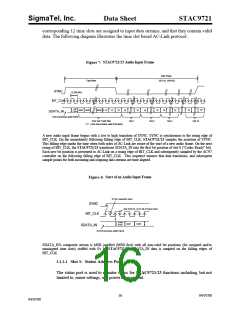
Audio input frame slot 1’s stream echoes the control register index, for historical
reference, for the data to be returned in slot 2. (Assuming that slots 1 and 2 had been
tagged “valid” by STAC9721/23 during slot 0)
Status Address Port hit assignments:
Bit (19)
RESERVED Stuffed with 0)
Bit (18;12)
returned)
Bit (11:0)
Control Register Index (Echo of register index for which data is being
RESERVED (Stuffed with 0's)
The first bit (MSB) generated by STAC9721/23 is always stuffed with a 0. The following
7 bit positions communicate the associated control register address, and the trailing 12 bit
positions are stuffed with 0's by STAC9721/23.
3.1.2.2 Slot 2: Status Data Port
The status data port delivers 16-bit control register read data.
Bit (19:4) Control Register Read Data (Stuffed with 0's if tagged "invalid")
Bit (3 :0) RESERVED
(Stuffed with 0's)
If Slot 2 is tagged "invalid" by STAC9721/23, then the entire slot will be stuffed with 0's.
Slot 3: PCM Record Left Channel
Audio input frame slot 3 is the left channel output of STAC9721/23 input MUX, post-
ADC.
STAC9721/23 ADCs are implemented to support 18-bit resolution.
STAC9721/23 outputs its ADC data (MSB first), and stuffs any trailing non-valid bit
positions with 0's to fill out its 20-bit time slot.
3.1.2.3 Slot 4: PCM Record Right Channel
Audio input frame slot 4 is the right channel output of STAC9721/23 input MUX, post-
ADC.
STAC9721/23 outputs its ADC data (MSB first), and stuffs any trailing non-valid bit
positions with 0's to fill out its 20-bit time slot.
3.1.2.4 Slots 5-12: Reserved
Audio input frame slots 5-12 are not used by the STAC97908/11 and are always stuffed
with 0's.
17
04/07/00
04/07/00

 ETC [ ETC ]