SigmaTel, Inc.
Data Sheet
STAC9721
3.1.1.9 Slot 9: PCM Low Frequency Channel
Audio output frame slot 9 is the composite digital audio low frequency stream used in a
multi-channel application where the STAC9721/23 has been programmed to accept the
DAC DAC PCM data from slots 6 and 9. Please refer to the register programming
section for details on the multi-channel programming options.
3.1.1.10 Slot 10: PCM Alternate Left
Audio output frame slot 10 is the composite digital audio alternate left stream used in a
multi-channel application where the STAC9721/23 has been programmed to accept the
DAC PCM data from slots 10 and 11. Please refer to the register programming section
for details on the multi channel programming options.
3.1.1.11 Slot 11: PCM Alternate Right
Audio output frame slot 11 is the composite digital audio alternate right stream used in a
multi-channel application where the STAC9721/23 has been programmed to accept the
DAC PCM data from slots 10 and 11. Please refer to the register programming section
for details on the multi channel programming options.
3.1.1.12 Slot 12: Reserved
Audio output frame slot 12 is reserved for modem operations and is not used by the
STAC9721/23.
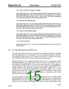
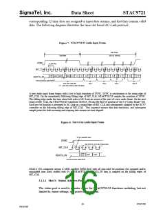
3.1.2 AC-Link Audio Input Frame (SDATA_IN)
The audio input frame data streams correspond to the multiplexed bundles of all digital
input data targeting the AC'97 controller. As is the case for audio output frame, each AC-
Link audio input frame consists of 12, 20-bit time slots. Slot 0 is a special reserved time
slot containing 16 bits that are used for AC-Link protocol infrastructure.
Within slot 0 the first bit is a global bit (SDATA_IN slot 0, bit 15) which flags whether
the STAC9721/23 is in the "Codec Ready" state or not. If the “Codec Ready” bit is a 0,
this indicates that STAC9721/23 is not ready for normal operation. This condition is
normal following the de-assertion of power on reset, for example, while STAC9721/23’s
voltage references settle. When the AC-Link "Codec Ready" indicator bit is a 1, it
indicates that the AC-Link and STAC9721/23 control/status registers are in a fully
operational state. The AC'97 controller must further probe the Powerdown Control Status
Register index 26h (refer to Mixer Register section) to determine exactly which
subsections, if any, are ready.
Prior to any attempts at putting STAC9721/23 into operation the AC'97 controller should
poll the first bit in the audio input frame (SDATA_IN slot 0, bit 15) for an indication that
STAC9721/23 has become "Codec Ready". Once the STAC9721/23 is sampled "Codec
Ready", the next 12 bit positions sampled by the AC'97 controller indicate which of the
15
04/07/00
04/07/00

 ETC [ ETC ]