SigmaTel, Inc.
Data Sheet
STAC9721
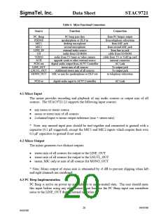
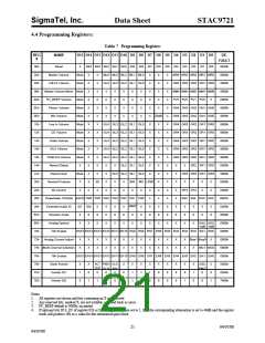
. Mixer Functional Connections
Table 6
Source
Function
Connection
PC_Beep
PHONE
MIC1
PC beep pass thru
speakerphone or DLP in
desktop microphone
from PC beeper output
from telephony subsystem
from MIC jack
MIC2
second microphone
from second MIC jack
from line-in jack
LINE_IN
CD
external audio source
audio from CD-ROM
cable from CD-ROM
cable from TV or VidCap card
internal connector
VIDEO
AUX
audio from TV tuner or video camera
upgrade synth or other external source
PCM out
digital audio output from AC'97 Controller
stereo mix of all sources
AC-Link
LINE_OUT
LNLVL_OUT
MONO_OUT
To output jack
Additional stereo mix of all sources
MIC or mix for speakerphone or DLP out
To output jack
to telephony subsystem
PCM in
digital audio input to AC'97 Controller
AC-Link
4.1 Mixer Input
The mixer provides recording and playback of any audio sources or output mix of all
sources. The STAC9721/23 supports the following input sources:
• any mono or stereo source
• mono or stereo mix of all sources
• 2-channel input w/mono output reference (mic + stereo mix)
* Note: any unused input pins should be tied together and connected to ground with a
capacitor (0.1 µF suggested), except the MIC1 and MIC2 inputs which require their own
0.1 µF capacitors to ground if not used.
4.2 Mixer Output
The mixer generates two distinct outputs:
• stereo mix of all sources for output to the LINE_OUT
• stereo mix of all sources for output to the LNLVL_OUT
• mono, MIC only or mix of all sources for MONO_OUT
* Note: Mono output of stereo mix is attenuated by -6 dB to prevent clipping when left
and right channels are combined.
4.3 PC Beep Implementation
PC Beep is active on power up and defaults to an un-muted state. The user should mute
this input before using any other mixer input because the PC Beep input can contribute
noise to the LINE_OUT during normal operation.
20
04/07/00
04/07/00

 ETC [ ETC ]