SigmaTel, Inc.
Data Sheet
STAC9721
corresponding 12 time slots are assigned to input data streams, and that they contain valid
data. The following diagram illustrates the time slot based AC-Link protocol.
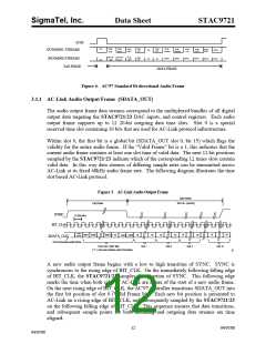
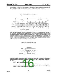
. STAC9721/23 Audio Input Frame
Figure 7
Data Phase
Tag Phase
20.8 uS (48 kHZ)
SYNC
12.288 MHz
BIT_CLK
valid
Frame
slot1 slot2
slot(12)
19
19
"0"
"0"
"0"
"0"
19
"0"
19
"0"
"0"
SDATA_IN
End of previous audio frame
Time Slot "Valid" Bits
("1" = time slot contains valid PCM data)
Slot 1
Slot 2
Slot 3
Slot 12
A new audio input frame begins with a low to high transition of SYNC. SYNC is synchronous to the rising edge of
BIT_CLK. On the immediately following falling edge of BIT_CLK, STAC9721/23 samples the assertion of SYNC.
This falling edge marks the time when both sides of AC-Link are aware of the start of a new audio frame. On the next
rising of BIT_CLK, the STAC9721/23 transitions SDATA_IN into the first bit position of slot 0 ("Codec Ready" bit).
Each new bit position is presented to AC-Link on a rising edge of BIT_CLK and subsequently sampled by the AC'97
controller on the following falling edge of BIT_CLK. This sequence ensures that data transitions, and subsequent
sample points for both incoming and outgoing data streams are time aligned.
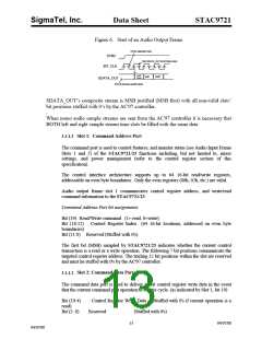
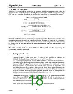
. Start of an Audio Input Frame
Figure 8
SYNC assertion here
SYNC
first SDATA_OUT bit of frame here
BIT_CLK
Codec
slot1
slot2
Ready
SDATA_IN
End of previous audio frame
SDATA_IN's composite stream is MSB justified (MSB first) with all non-valid bit positions (for assigned and/or
unassigned time slots) stuffed with 0's by STAC9721/23. SDATA_IN data is sampled on the falling edges of
BIT_CLK.
3.1.2.1 Slot 1: Status Address Port
The status port is used to monitor status for STAC9721/23 functions including, but not
limited to, mixer settings, and power management.
16
04/07/00
04/07/00

 ETC [ ETC ]