Ver 1.3
PRELIMINARY
EAGLE
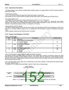
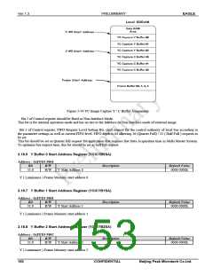
Figure 3-34 YC Image Capture Y / C Buffer Assignment
Bit 2 of Control register should be fixed as Non-Interlace Mode.
This bit is for internal operation mode and has no ties to the Interlace or Non-Interlace mode of external image.
Bit 3 of Control register, FIFO Request Level Setting Bit, shall request for the control authority of local bus according to
the parameter settings as well as current FIFO level. FIFO depth is 64 allowing 16 (Quarter Full) / 32 ( Half Full ) requests to
be set.
This bit should be set as Quarter full request for application that requires fast Data Acquisition time in Multi Master System.
To optimize bus request time, this bit should be set as half full request.
3.18.6 Y Buffer 0 Start Address Register (YCICYB0SA)
Address : 0xFFE0 5804
Bit
R/W
Description
Default Value
31:0
R/W
Y Start Address 0
0000 0000h
Y ( Luminance ) Frame Memory start address 0
3.18.7 Y Buffer 1 Start Address Register (YCICYB1SA)
Address : 0xFFE0 5808
Bit
R/W
Description
Default Value
31:0
R/W
Y Start Address 1
0000 0000h
Y ( Luminance ) Frame Memory start address 1
3.18.8 Y Buffer 2 Start Address Register (YCICYB2SA)
Address : 0xFFE0 580C
Bit
R/W
Description
Default Value
31:0
R/W
Y Start Address 2
0000 0000h
Y ( Luminance ) Frame Memory start address 2
153
CONFIDENTIAL
Beijing Peak Microtech Co.Ltd.

 ETC [ ETC ]