EAGLE
PRELIMINARY
Ver 1.3
3.18.4 Operational Descriptions
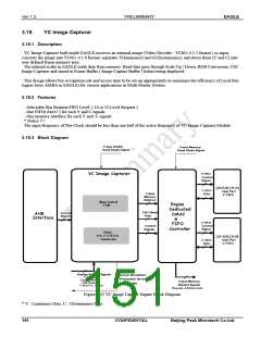
YC Image Capturer consists mainly of AHB Interface Module, Engine Core, Engine DMAC & FIFO Controller and 64x32
Dual Port Y(C) FIFO.
1) AHB Interface Module :
This is a bus interface module for upper-layer AMBA and includes a register bank.
These register are used as signal controls for Engine operation and to report current module state of Master Device.
2) YC Image Capturer Core:
The Engine Core consists mainly of Main Control FSM and YCbCr 4:2:2 to 4:2:0 Converter.
Main Control FSM receives signals related to external image, such as Sync, Display, etc., controls the entire Engine
operations, and transfers Source/Destination Resolution and Scale Buffer information to Scaler. The YCbCr 4:2:2 to 4:2:0
converter converts external images in YCbCr 4:2:2 format to 4:2:0 Format.
3) Engine DMAC & FIFO Controller:
The DMA Controller Engine executes the bus request based on the Bus Request FIFO Level configuration as well as the
FIFO Level. To acquire authority control of bus, it communicates with the Memory Controller to determine the Request
Level.
FIFO Controller controls the 64x32 Dual Port Sync Y(C) FIFO.
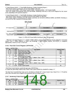
3.18.5 Engine Control Register (YCICCON)
Address : 0xFFE0 5800
Bit
31:4
3
R/W
R
R/W
Description
Default Value
Reserved.
-
FIFO Request Level Setting Bits.
0: Level 32 Request
1: Level 16 Request
Non Interlace Setting Bit.
0: Disable
0b
0b
2
R/W
1: Enable
1
0
R/W
R/W
YC Image Capture Mode
Engine Enable
0b
0b
0: Disable
1: Enable
Bit 0 of Control register, Engine Enable bit, enables and disables the Engine.
All parameter should be set before setting the enable bit. Once enabled, there should be no parameter changes that might
affect the Engine operation. YC Image Capturer operates in unit Frame. When the Enable bit is cleared during the Engine
operation, the current YC Image Capturer operation in progress should continue and Engine shall transit to the Idle state once
the current frame operation ends.
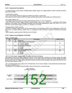
Bit 1 of Control register selects input source of Scaler block. If user wants to display or scale up/down the external images,
this register should be set as ‘1’.
Switching of YC ICE Buffer and Scaler Buffer is done by Vertical Sync of external image.
Figure 3-33 YC Image Capturer Buffer and Scaler Buffer Switching & Pipe Line Operation
Beijing Peak Microtech Co.Ltd.
CONFIDENTIAL
152

 ETC [ ETC ]