EAGLE
PRELIMINARY
Ver 1.3
1. Control Register bit[4] = 1 / Front Buffer Rendering ( Graphic Rendering Engine )
JPEG Image Capture is performed, and one Frame Buffer is allocated.
In this case, Frame Buffer = JPEG Image Capturer Buffer = Rendering Buffer = CRT Display Buffer.
Since CRT Display and Rendering shares the same Buffer, Rendering result may or may not be displayed on the current
screen, depending on the operation sequence.
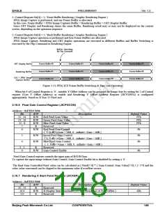
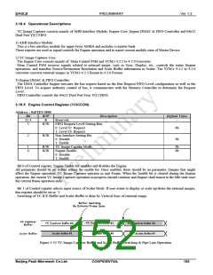
2. Control Register bit[4] = 1 / Back Buffer Rendering ( Graphic Rendering Engine )
JPEG Image Capture operation is performed and four Frame Buffers are allocated.
JPEG Image Capture, Rendering and CRT display operations are executed in different Buffers and Buffer Switching is
executed by the Flip Command in Rendering Engine.
Buffer Switching
By Flip Command
CRT Display Buffer
Rendering Buffer
Frame Buffer #0
Frame Buffer #1
Frame Buffer #2
Frame Buffer #1
Frame Buffer #2
Frame Buffer #3
Frame Buffer #2
Frame Buffer #3
Frame Buffer #0
Frame Buffer #3
Frame Buffer #0
Frame Buffer #1
CSC / JPEG Image
Capture Buffer
Figure 3-31 JPEG ICE Frame Buffer Switching & Pipe Line Operation
When bit 4 of Control Register is ‘0’, suitable Y Offset Address can be assigned for Image Size by setting bit 2 of Control
register (User Y Offset Address) as enable and Rendering Y Offset Address Register (JICYOFFA) is configured
appropriately based on X Size 32 Pixel unit.
3.16.6 Pixel Gain Control Register (JICPGCON)
Address : 0xFFE0 5004
Bit
31 : 24
23 : 16
15 : 8
7
R/W
R/W
R/W
R/W
R
Description
Default Value
Red Pixel Gain Value
Green Pixel Gain Value
Blue Pixel Gain Value
Reserved
FFh
FFh
FFh
-
6
R/W
Red Pixel Gain Control
0b
( 1: 0 dB<=Gain < 3dB, 0: -infinite< Gain < 0dB )
5
4
R/W
R/W
Green Pixel Gain Control
( 1: 0 dB<=Gain < 3dB, 0: -infinite< Gain < 0dB )
Blue Pixel Gain Control
0b
0b
( 1: 0 dB<=Gain < 3dB, 0: -infinite< Gain < 0dB )
Reserved
Gain Control Enable
3 : 1
0
R
R/W
-
0b
Pixel Gain Control register controls the input gain of R/G/B Data.
To capture the input image without Gain Control, Gain Control Enable bit is disabled by setting a ’0’.
The final Gain Controlled Pixel value can be calculated as [ Pixel[7:0] * { Gain Control, Gain Value[7:0] } ] / 2^8 and the
color value concerned can be clipped to the maximum value if overflow occurs.
3.16.7 Rendering X Start Point Register (JICXSP)
Address : 0xFFE0 5008
Bit
31 : 11
10:4
R/W
R
R/W
R
Description
Default Value
Reserved
-
00h
-
X Display Start Coordinate [10:4] ( Horizontal 16 Pixel Offset )
Reserved
3:0
Beijing Peak Microtech Co.Ltd.
CONFIDENTIAL
148

 ETC [ ETC ]