Power Driver Integrated Full Digital Audio Amplifier
NTP-8230
6. CLOCK, RESET & CONTROL
6.1. System Clock
The internal system clock of the NTP-8230 is generated from an external master clock by the on-chip
PLL. The NTP-8230 supports external master clock frequency from 2.048 MHz to 24.576MHz. For
proper operation, the registers for the PLL should be set correctly according to master clock frequency
(Address 0x02).
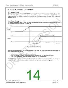
6.2. Reset Timing
For proper initialization of NTP-8230, the reset signal should be low more than 0.1usec when the 3.3V
I/O supply is stabilized as shown in Figure 10.
3.3V
I/O supply
voltage
(VDD_IO)
0V
~7us
3.3V
RESET
0V
Normal
Operation
Initialization
T1
T1>>0.1usec
Figure 10. Reset Timing
While in normal operation, if /RESET pin is set to a low state, the NTP-8230 enters the reset state to
bring up the actions as follows.
1) Each control register resets to the default value.
2) All the internal registers, multipliers, adders, counters, and etc. are cleared to zero.
3) All of the output pins keep low state as long as the /RESET is active.
The /RESET pin should be maintained in the low state more than 0.1usec, and it takes around 7µs to
initialize the NTP-8230 after the reset pin is raised to the high state as shown in Figure 10.
Copyright ⓒ NeoFidelity, Inc.
Page 14
Document Number: DS8230 draft ver. 0.1
2011-01-11

 ETC [ ETC ]