Power Driver Integrated Full Digital Audio Amplifier
NTP-8230
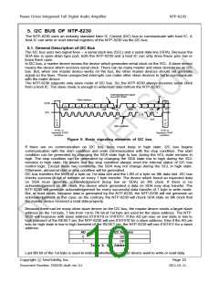
5.1.1. Writing Operation
When last 8th bit of the 1st byte is set to low state, the writing operation of I2C bus begins. The NTP-
8230 supports 3 kind of writing operations which presented on Figure 6
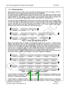
The type presented on Figure 6-(a) is single byte write operation. “Sub address” on 2nd byte means
the internal register address of the NTP-8230. The “Data” on 3rd byte will be written into the internal
register address on “Sub address”. If stop condition is not generated, writing “data” on specific “sub
address” can be repeated like Figure 6-(b). “Data #n” will be written on “sub address #n”.
The type presented on Figure 6-(c) is burst byte write operation under address auto increment mode.
The AIF is the address Auto Increment Flag which is 1st bit of 2nd byte of I2C packet. On SDA, if AIF
is set to high state, the NTP-8230 starts auto incrementing the address with respect to given “sub
address” and host send write data continuously over SDA. In AIF mode, access to the register
addresses 0x3B~0x49, 0x4F and 0x5E are automatically skipped.
(a)
S
Slave address
Slave address
Slave address
W
W
W
A AIF Sub Address
A
A
A
Data
Data #1
Data #1
A
A
A
P
(b)
S
A AIF Sub Address #1
AIF Sub Address #2
A
Data #2
A
P
(c)
S
A AIF
Sub Address #1
Data #n
A P
Figure 6. Single Byte Write Mode Sequence
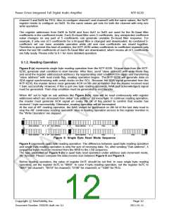
Figure 7-(a), Figure 7-(b), and Figure 7-(c) represent 4 byte writing operations. Coefficient Mode
Register address 0x00~0x6B are used to configure Bi-Quad filter coefficients, Low Shelf BQ filter
coefficients, Loudness gains and DRC clip down gain. The data size of these coefficients and gains is
4 byte for each. The difference between 4byte writing operation and single byte writing operation is
only the size of transferring data. So, after sending “Sub address”, 4 sequential bytes must be
transferred from the MSB(most significant byte) to the LSB(least significant byte) sequence.
The type presented on Figure 7-(c) is quad byte write operation under address auto increment mode,
AIF function. Please compare the data transfer size between Figure 6 and Figure 7.
(a)
A
P
S
Slave address
Slave address
W
W
A
A
AIF Sub Address
A
Data (Byte #4)
Data (Byte #3)
Data (Byte #2)
A
Data (Byte #1)
A
A
b
(
)
A
A
S
AIF Sub Address #1
AIF Sub Address #n
A
A
Data (Byte #4)
Data (Byte #3)
Data (Byte #2)
A
A
Data (Byte #1)
A
A
A
A
Data #n (Byte #4)
Data #n (Byte #3)
Data #n (Byte #2)
Data #n (Byte #1)
P
(c)
A
A
S
Slave address
W
A
AIF Sub Address
Data #n-1 (Byte #1)
A
A
Data (Byte #4)
Data (Byte #3)
Data (Byte #2)
A
A
Data (Byte #1)
A
A
A
Data #n (Byte #4)
Data #n (Byte #3)
Data #n (Byte #2)
Data #n (Byte #1)
P
Figure 7. Quad Byte Write Mode Sequences
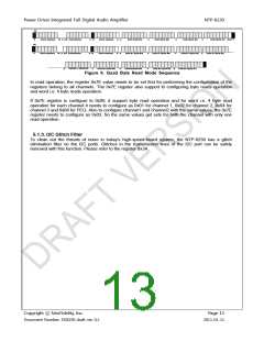
In write operation, the register 0x7E value needs to be set first for performing the configuration of the
registers belong to all channels. The 0x7E register also support to configuring byte writes operation
and word i.e. 4 byte writes operation.
If 0x7E register is configure to 0x00, it support byte write operation and for word i.e. 4 byte write
operation for each channel it needs to configure as 0x01 for channel 1, 0x02 for channel 2, 0x04 for
Copyright ⓒ NeoFidelity, Inc.
Page 11
Document Number: DS8230 draft ver. 0.1
2011-01-11

 ETC [ ETC ]