Power Driver Integrated Full Digital Audio Amplifier
NTP-8230
5. I2C BUS OF NTP-8230
The NTP-8230 uses an industry standard Inter IC Control (I2C) bus to communicate with host IC. A
host IC can write or read internal registers of the NTP-8230 via the I2C bus.
5.1. General Description of I2C Bus
The I2C bus uses two signal lines – a serial clock line (SCL) and a serial data line (SDA). Because the
SDA line is open-drain type port, both the NTP-8230 and a host IC can only drive these pins low or
leave them open.
In I2C bus, a master device means the device which generates serial clock on the SCL. A slave device
means the device which receives serial clock. There can be many master and slave devices on an I2C
bus. But, when one master device works on the bus, the other master devices should not generate
signal on the lines. These unexpected interrupts can make other slave devices to fail to communicate
with the mater device.
The NTP-8230 supports only slave mode of I2C bus. So, the NTP-8230 always receives serial clock
from a host IC. The slave mode is enough to write/read data to/from the NTP-8230.
Acknowledgement signal
From NTP-8230
R
A
Slave address
Sr
P
SDA
SCL
…
0
1
2
0
3
1
4
0
5
1
6
0
MSB
LSB
MSB
LSB
W
…
A
1
7
8
9
1
2-8
9
ACK
ACK
Sr
S
or
Sr
or
P
Byte complete
START or
Repeated START
condition
STOP or
Repeated START
condition
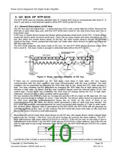
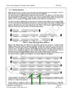
Figure 5. Basic signaling elements of I2C bus
If there are no communication on I2C bus, lines must keep in high state. I2C bus begins
communication with the start condition and ends communication with the stop condition. The start
condition can be generated by changing the SDA state high to low, during the SCL state remains in
high. The stop condition can be generated by changing the SDA state low to high during the SCL
remains in high state. Be aware that the stop condition always reset the internal status of I2C bus
control logic. Except these two conditions, the SDA may not change during the SCL in high state.
Otherwise, abnormal start or stop condition will be generated.
I2C bus transfers the MSB of a byte on 1st data slot and the LSB of a byte on 8th data slot. I2C bus
checks success or fail of transfer on every 1 byte transfer. The device which found an expected data
on SDA must generate acknowledgement (keep low on SDA) on 9th clock. If there is no
acknowledgement on 9th clock, the device which generated a data on SDA may stop transfer. The
NTP-8230 will generate acknowledgement for every successful data transfer of 1 byte in write mode.
But, in read mode, because data is generated by the NTP-8230, the NTP-8230 will not generate an
acknowledgement. In this case, on the contrary, the NTP-8230 will check SDA state on 9th clock that
the master device received a read data properly.
Because there can be many other slave device on the I2C bus, the master device sends a target slave
address on the 1st byte. 7 bits from 1st to 7th bit of 1st byte are used for the slave address. The NTP-
8230 will response with slave address 0101010 or 0101011. If the AD pin was on low state in low to
high transient of the RESET pin, the NTP-8230 will use 0101010 for a slave address. Else if the AD pin
was on high state in low to high transient of the RESET pin, the NTP-8230 will use 0101011 for a slave
address.
AD
I2C Address
0
0x54
0x56
1
Table 2. I2C Address
Last 8th bit of the 1st byte is used to indicate whether the master device want to write or read data.
Copyright ⓒ NeoFidelity, Inc.
Page 10
Document Number: DS8230 draft ver. 0.1
2011-01-11

 ETC [ ETC ]