Power Driver Integrated Full Digital Audio Amplifier
NTP-8230
channel 3 and 0x08 for PEQ. Also to configure channel1 and channel2 with the same values, the 0x7E
register needs to configure as 0x03. So the same values get sets for both the channel with only one
write operation.
The register addresses from 0x00 to 0x3B and from 0x41 to 0x63 are used for the Bi-Quad filter
coefficients in the coefficient mode. Each Bi-Quad filter uses 5 coefficients. Any unexpected coefficient
value changes on any part of 5 coefficients can generate unstable Bi-Quad filter response. For
example, if only one of 5 coefficients for a Bi-quad filter is changed and downloaded, its combined 5-
coefficient set can have unstable operation while old and new coefficients are mixed together.
Therefore to prevent this kind of problem, the NTP-8230 writes coefficients to coefficient registers only
when the last 5th coefficients of each Bi-Quad filter are downloaded, which means all of 5 coefficients
are fully ready. Please refer to 9.1 for more detailed operation.
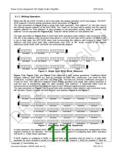
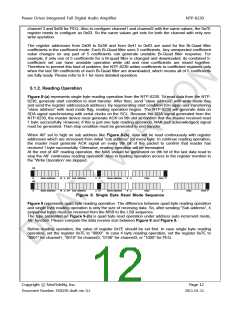
5.1.2. Reading Operation
Figure 8-(a) represents single byte reading operation from the NTP-8230. To read data from the NTP-
8230, generate start condition to start transfer. After then, send “slave address” with write mode flag
and send the register address(sub address). By regenerating start condition (Sr) again and transferring
“slave address” with read mode flag, reading operation begins. The NTP-8230 will generate data on
SDA signal synchronizing with serial clocks on the SCL. Because the SDA signal generated from the
NTP-8230, the master device must generate ACK on 9th slot to confirm that the master received read
1 byte successfully. However, if this is just one byte reading operation, NAK (not acknowledged) signal
must be generated. Then stop condition must be generated to end transfer.
When AIF set to high on sub address like Figure 8-(b), data will be read continuously with register
addresses which are increased from initial “sub address” for every byte. In continue reading operation,
the master must generate ACK signal on every 9th bit of the packet to confirm that master has
received 1 byte successfully. Otherwise, reading operation will be terminated.
At the end of AIF reading operation, the NAK should be generated on 9th bit of the last data read to
stop the AIF continuous reading operation. Also in reading operation access to the register mention in
the “Write Operation‟ are skipped.
(a)
S
Slave address
Slave address
W
W
A
AIF Sub address
A
Sr
Slave address
R
A
Data
NAK
P
(b)
S
A AIF Sub address
A
Sr
Slave address
R
A
Data
A
Data
NAK P
Figure 8. Single Byte Read Mode Sequence
Figure 9 represents quad byte reading operation. The difference between quad byte reading operation
and single byte reading operation is only the size of receiving data. So, after sending “Sub address”, 4
sequential bytes must be received from the MSB to the LSB sequence.
The type presented on Figure 9-(b) is quad byte read operation under address auto increment mode,
AIF function. Please compare the data receive size between Figure 8 and Figure 9.
Before reading operation, the value of register 0x7E should be set first. In case single byte reading
operation, set the register 0x7E to “0000”. In case 4 byte reading operation, set the register 0x7E to
“0001” for channel1, “0010” for channel2, “0100” for channel3, or “1000” for PEQ.
Copyright ⓒ NeoFidelity, Inc.
Page 12
Document Number: DS8230 draft ver. 0.1
2011-01-11

 ETC [ ETC ]