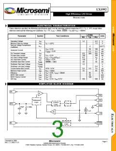
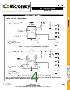
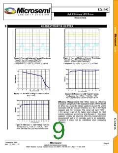
LX1992
High Efficiency LED Driver
L I N F I N I T Y D I V I S I O N
PRODUCTION
APPLICATION INFORMATION
PCB LAYOUT
formula for ∆VDROOP is:
The LX1992 produces high slew-rate voltage and current
waveforms hence; the designer should take this into
consideration when laying out the circuit. Minimizing trace
lengths from the IC to the inductor, transistor, diode, input
and output capacitors, and feedback connection (i.e., pin 6)
are typical considerations. Moreover, the designer should
maximize the DC input and output trace widths to
accommodate peak current levels associated with this
topology.
L
×
(
IPK × IOUT
)
= COUT
∆VDROOP
(
VIN − 0.5)
The output overshoot can be estimated as follows where the
0.5 value in the denominator is an estimate of the voltage
drop across the diode:
L
2
1
×
×
IPK − IOUT
( )
2
EVALUATION BOARD
COUT
∆VOVERSHOOT
DESIGN EXAMPLE:
Determine the VRIPPLE where IPK equals 200mA, IOUT
equals 12.8mA, L equals 47µH, COUT equals 4.7µF, VIN
equals 3.0V, and VOUT equals 13.0V:
=
The LXE1992 evaluation board is available from
Microsemi for assessing overall circuit performance. The
evaluation board, shown in Figure 3, is 3 by 3 inches (i.e.,
7.6 by 7.6cm) square and programmed to drive 4 LEDs
(provided). Designers can easily modify circuit parameters
to suit their particular application by replacing RCS (as
described in this section) RSET (i.e., R4) and diode load.
Moreover, the inductor, FET, and switching diode are easily
swapped out to promote design verification of a circuit that
maximizes efficiency and minimizes cost for a specific
(
VOUT + 0.5 − V
)
IN
47µH
4.7µF
×
200mA×12.8mA
( )
∆VDROOP
=
≅ 10.2mV
(
3.0 − 0.5)
application.
The evaluation board input and output
47µH
4.7µF
2
1
connections are described in Table 1.
×
2
×
(
200mA −12.8mA
)
The DC input voltage is applied to VBAT (not VCC)
however the LX1992 IC may be driven from a separate DC
source via the VCC input. The output current (i.e., LED
brightness) is controlled by adjusting the on-board
∆VOVERSHOOT
=
≅ 18.4mV
(
13.0 + 0.5 − 3.0)
Therefore, VRIPPLE = 10.2mV + 18.4mV + 10mV = 38.6mV
DIODE SELECTION
potentiometer.
The designer may elect to drive the
brightness adjustment circuit from VBAT or via a separate
voltage source by selecting the appropriate jumper position
(see Table 2). Optional external adjustment of the output
LED current is achieved by disengaging the potentiometer
and applying either a DC voltage or a PWM-type signal to
the VADJ input. The PWM signal frequency should be
higher than 150KHz and contain a DC component les than
350mV.
A Schottky diode is recommended for most applications
(e.g. Microsemi UPS5817). The low forward voltage drop
and fast recovery time associated with this device supports
the switching demands associated with this circuit
topology. The designer is encouraged to consider the
diode’s average and peak current ratings with respect to
the application’s output and peak inductor current
requirements. Further, the diode’s reverse breakdown
voltage characteristic must be capable of withstanding a
The LX1992 exhibits a low quiescent current (IQ < 0.5µA:
typ) during shutdown mode. The SHDN pin is used to
exercise the shutdown function on the evaluation board.
This pin is pulled-up to VCC via a 10KΩ resistor.
Grounding the SHDN pin shuts down the IC (not the circuit
output). The output voltage (i.e., voltage across the LED
string) is readily measured at the VOUT terminal and LED
current is derived from measuring the voltage at the VFDBK
pin and dividing this value by 15Ω (i.e., R4).
negative voltage transition that is greater than VOUT
.
TRANSISTOR SELECTION
The LX1992 can source up to 100mA of gate current.
An N-channel MOSFET with a relatively low threshold
voltage, low gate charge and low RDS(ON) is required to
optimize overall circuit performance. The LXE1992
Evaluation Board uses a Fairchild FDV303. This NMOS
device was chosen because it demonstrates an RDS_ON of
0.33Ω and a total gate charge Qg of 1.64nC (typ.)
The factory installed component list for this must-have
design tool is provided in Table 3 and the schematic is
shown in Figure 4
Copyright 2000
Rev. 1.1, 2002-11-21
Microsemi
Page 6
Linfinity Microelectronics Division
11861 Western Avenue, Garden Grove, CA. 92841, 714-898-8121, Fax: 714-893-2570

 ETC [ ETC ]