SPI-8001TW/SPI-8002TW/SPI-8003TW
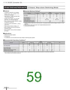
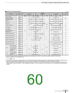
■Electrical Characteristics*1
(Ta=25°C)
Ratings
Parameter
Symbol
SPI-8001TW
typ.
SPI-8002TW
typ.
SPI-8003TW
typ.
Unit
min.
max.
min.
max.
min.
max.
VREF
0.996
1.006
1.016
0.996
1.006
1.016
0.966
1.006
1.016
Reference Voltage
V
mV/°C
%
Conditions
∆VREF/∆T
Conditions
Eff1
VIN=10V, VO=1V, IO=0.1A
VIN=14V, IO=0.1A
±0.1
Temperature Coefficient
of Reference Voltage
±0.1
±0.1
VIN=10V, VO=1V, IO=0.1A, Ta=–30 to +135°C
VIN=14V, IO=0.1A, Ta=–30 to +125°C
80
78
78
Efficiency 1*2
Conditions
Eff2
VIN=VCC=15V, VO=5V, IO=0.5A, IIN: including ICC
VIN= VCC=14V, VO=5V, IO=0.5A, IIN : including ICC
83
81
81
Efficiency 2*2
%
Conditions
fosc
VIN=15V, VO=5V, IO=0.5A, VCC=5V, IIN: excluding ICC
V
IN=14V, VCC=5V, V
O
=5V, I
O
=0.5A, IIN : excluding ICC
400
250
30
215
250
285
60
200
Oscillation Frequency
Line Regulation
Load Regulation
kHz
mV
mV
A
Conditions
VLINE
VIN=VCC=15V, VO=5V, IO=0.5A
VIN=14V, IO=0.1A, COSC=100pF
30 60
VIN=VCC=9 to 18V, VO=5V, IO=1A
60
30
10
Conditions
VLOAD
VIN=VCC=10 to 20V, VO=5V, IO=1A
40
10
40
10
=5V, I
40
Conditions
IS
VIN=VCC=15V, VO=5V, IO=0.2 to 1.5A
VIN=VCC=14V, V
O
O
=0.2 to 1.5A
Overcurrent Protection
Starting Current
1.6
1.6
1.6
Conditions
IIN
VIN=VCC=15V
VIN=VCC=14V
4
4
4
Quiescent Circuit Current 1
Quiescent Circuit Current 2
Quiescent Circuit Current 3
Quiescent Circuit Current 4
Quiescent Circuit Current 5
Quiescent Circuit Current 6
mA
mA
µA
µA
mA
mA
V
Conditions
ICC
VIN=15V, VCC=5V, IO=0V, VO≤12V
VIN=14V, VCC=5V, IO=0A, VO≤12V
8.5
8.5
8.5
Conditions
IIN (off)
VCC=15V, IO=0A
VCC=14V, IO=0A
1
1
1
1
Conditions
ICC (off)
VIN=15V, VC/E=0V or Open
VIN=14V, VC/E=0V or Open
1
1
Conditions
IIN (ssov)
VCC=15V, VC/E=0V or Open
VIN=14V, VC/E=0V or Open
—
4
Conditions
ICC (ssov)
Conditions
VC/EH
—
VIN=14V, VCC=5V, IO=0A, SS1=SS2=0V
—
8.5
—
VCC=14V, IO=0V, SS1=SS2=0V
2
2
2
High Level Voltage
Conditions
VC/EL
VIN=VCC=15V
0.8
VIN=VCC=14V
0.8
0.8
C/E Pin
SS Pin*3
Low Level Voltage
V
Conditions
IC/EH
VIN=VCC=15V
VIN=VCC=14V
95
Inflow Current
at High
95
60
95
60
µA
V
Conditions
VSSL
VC/E=20V
VC/E=20V
0.5
0.5
0.5
80
Low Level Voltage
Conditions
ISSL
VIN=VCC=15V
80
VIN=VCC=14V
Inflow Current
at Low
60
80
µA
Conditions
VSSL=0V, VIN=VCC=15V
VSSL=0V, VIN=VCC=14V
*1: Electrical characteristics show the characteristic ratings guaranteed when operating the ICs under the measurement conditions described in the above table.
*2: Efficiency is calculated from the following formula.
VO·IO
VIN·IIN
η (%) =
× 100
*3: Pin 6 and pin 11 are the SS pins. Soft start at power on can be performed with capacitors connected to these pins. The outputs can also be turned ON/OFF with these pins. The
outputs are stopped by setting the voltages of these pins to VSSL or lower. SS-pin voltages can be changed with open-collector drive circuits of transistors.
When using both the soft-start and ON/OFF functions together, the discharge currents from C4 and C5 flow into the ON/OFF control transistors respectively. Therefore, limit the
currents securely to protect the transistors if C4 and C5 capacitances are large. The SS pins are pulled up to the power supply in the ICs, so applying the external voltages are
prohibited.
ICs
59

 ETC [ ETC ]