1-1-3 DC/DC Converter ICs
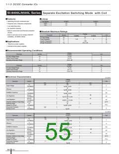
STA801M 2-Output Separate Excitation Switching Mode
■Features
■Lineup
• 2 regulators combined in 1 package
Output Voltage (V)
Part Number
STA801M
Ch1
5
Ch2(Select one output)
9.0 / 11.5 / 12.1 / 15.5
• Compact inline package
• Output current (0.5A × 2 outputs)
• Output voltage of Ch2 selectable from 4 levels
• Built-in flywheel diode (Schottky barrier diode)
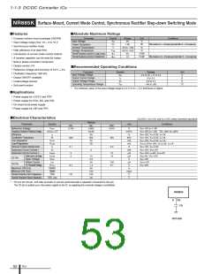
■Absolute Maximum Ratings
• Requires only 7 discrete components (2
outputs)
Parameter
Symbol
Ratings
Unit
DC Input Voltage
VIN
43
6.7(With infinite heatsink)
1.6(Without heatsink, stand-alone operation)
+125
V
PD1
PD2
Tj
W
W
°C
°C
• Internally-adjusted phase corrections and output
voltages
Power Dissipation
Junction Temperature
Storage Temperature
• Built-in reference oscillator (125kHz) - Enables
to downsize a choke-coil due to IC's high
oscillating frequency. (Compared with conven-
tional Sanken devices)
Tstg
–40 to +125
• Built-in overcurrent and thermal protection circuits
• Built-in soft start circuits (Output ON/OFF available)
■Applications
• For BS and CS antenna power supplies
• For stabilization of the secondary stage of switching power supplies
• Electronic equipment
■Recommended Operating Conditions
Ratings
Parameter
Symbol
Unit
min.
max.
40
DC Input Voltage Range
VIN
IO
Ch2 VOmax.+2
V
A
Output Current Range per Channel
Operating Temperature Range
0
0.5
Tjop
–20
+125
°C
■Electrical Characteristics
(Ta=25°C)
Ratings
STA801M
typ.
Parameter
Symbol
Unit
V
min.
4.80
max.
5.20
VO1
5.00
Output voltage 1
Efficiency *
Ch1
Conditions
η1
V
IN=20V, IO=0.3A
80
%
Conditions
V
IN=20V, IO=0.3A
Temperature Coefficient of Output Voltage
Line Regulation
∆V
O
/∆Ta1
0.5
30
mV/°C
∆VOLINE1
90
mV
mV
V
Conditions
∆VOLOAD1
Conditions
V
IN=10 to 30V, I
10
O=0.3A
40
Load Regulation
VIN=20V, I
O=0.1 to 0.4A
V
O
2-1
Conditions
2-2
Conditions
2-3
Conditions
2-4
8.64
11.04
11.62
14.88
9.00
9.36
11.96
12.58
16.12
Output voltage 2-1
Output voltage 2-2
Output voltage 2-3
Output voltage 2-4
Ch2
V
V
V
V
V
IN=20V, I
O
=0.3A
=0.3A
=0.3A
=0.3A
=0.3A
(Select one output)
V
O
11.50
V
IN=20V, I
12.10
IN=20V, I
15.50
O
V
O
V
O
V
O
V
Conditions
η
IN=20V, I
O
89
Efficiency*
VO
2-4
%
Conditions
IN=20V, I
O
Temperature Coefficient of Output Voltage
∆V
O
/∆T
a
2.0
40
mV/°C
∆VOLINE
130
120
Line Regulation
Load Regulation
mV
Conditions
∆VOLOAD
V
IN=20 to 30V, I
30
O=0.3A
mV
mA
Conditions
VIN=20V, I
O
=0.1 to 0.4A
Common
No-load Circuit Current
Oscillation Frequency
I
CC
15
f
125
0.7
kHZ
Overcurrent Protection Starting Current
I
S1
0.51
A
Icc
2
* Efficiency indicates the value when only one channel is active. The value can be calculated as shown below. 7.5mA is deducted for the no-load circuit current of
output.
at unused
VO•IO
VIN•(IIN–0.0075)
η=
× 100(%)
ICs
56

 ETC [ ETC ]