SLA2601M/SLA2602M
■Typical Connection Diagram
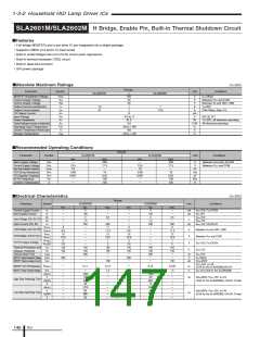
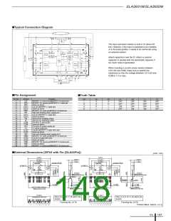
The input pull-down resistor is built in IC (about 22
kΩ). However, if the input is expected to be unstable
or to fluctuate greatly, it needs to be reinforced using
an external resistor.
Attach capacitors near the IC. Attach a ceramic
capacitor in parallel with the electrolytic capacitor if
too much noise is generated.
When inserting a current sense resistor between
LS1/LS2 and COM, make sure to specify the
resistance so that the voltage between LS1/LS2 and
COM is 1 V or less.
■Pin Assignment
■Truth Table
Pin No.
1
2
3
4
5
6
7
8
Symbol
LSI
Function
MOSFET L1 source pin/MOSFET L2 source pin
MOSFET H1 source pin/MOSFET L1 drain pin
Same as above
Cut pin (MOSFET L1 gate pin)
Same as above
MOSFET H1 drain pin/MOSFET H2 drain pin
High side floating power supply pin 1
Cut pin (MOSFET L1 gate pin)
Same as above
Input pin for enabling output
Input pin for switching output
Pre-drive IC ground pin
Same as above
Pre-drive IC power supply pin
Fo signal output pin
Cut pin (MOSFET L2 gate drive pin)
Same as above
High side floating power supply pin 2
MOSFET H1 drain pin/MOSFET H2 drain pin
Cut pin (L2 gate drive pin)
EN
L
X
H
H
IN
X
X
H
L
FO
X
H
L
H1
H2
L1
L2
OFF
OFF
ON
OFF
OFF
OFF
ON
OFF
OFF
OFF
ON
OFF
OFF
ON
VM1
VM1
(LG1)
(LG1)
VBB1
VB1
(LG1)
(LG1)
EN
L
OFF
OFF
9
10
11
12
13
14
15
16
17
18
19
20
21
22
23
24
IN
COM
COM
VCC
FO
(LG2)
(LG2)
VB2
VBB2
(LG2)
(LG2)
VM2
VM2
LS2
Same as above
MOSFET H2 source pin/MOSFET L2 source pin
Same as above
MOSFET L1 source pin/MOSFET L2 source pin
■External Dimensions (ZIP24 with Fin [SLA24Pin])
(Unit : mm)
31±0.2
31±0.2
4.8±0.2
1.7±0.1
4.8±0.2
1.7±0.1
24.4±0.2
16.4±0.2
Gate burr
24.4±0.2
16.4±0.2
Gate burr
φ3.2±0.15 X 3.8
φ3.2±0.15 X 3.8
φ3.2±0.15
φ3.2±0.15
JAPAN
JAPAN
A
B
A
B
2.45±0.2
(Measured at the root)
2.45±0.2
(Measured at the root)
4-(R1)
R-end
R-end
2-(R1)
+0.15
-0.05
+0.15
0.6
-0.05
+0.15
-0.05
+0.15
0.6
0.5
0.5
-0.05
23 X P1.27±0.7=29.21±1
4.5±0.7
23 X P1.27±0.7=29.21±1
2.5±0.6
(Measured at the tip)
(Measured at the tip)
(Measured at the tip)
(Measured at the tip)
31.3±0.2
31.3±0.2
Pins 4, 5, 8, 9, 16, 17, 20, and 21 are
cut pins.
Pins 4, 5, 8, 9, 16, 17, 20, and 21 are
cut pins.
(Including the resin burr)
(Including the resin burr)
Forming No. 2176
Forming No. 2179
2
4
6
8
10
12 14
13
16
18
20
22
24
2
4
6
8
10
12 14
13
16
18
20
22
24
1
3
5
7
9
11
15
17
19
21
23
1
3
5
7
9
11
15
17
19
21
23
Product Mass: Approx. 6.2 g
ICs
147

 ETC [ ETC ]