ST90158 - RESET AND CLOCK CONTROL UNIT (RCCU)
CLOCK MANAGEMENT (Cont’d)
6.3.4 Low Power Modes
tering WFI if the WFI_CKSEL bit has been set. It
should be noted that selecting a non-existent
CK_AF clock source is impossible, since such a
selection requires that the auxiliary clock source
be actually present and selected. In no event can
a non-existent clock source be selected inadvert-
ently.
The user can select an automatic slowdown of
clock frequency during Wait for Interrupt opera-
tion, thus idling in low power mode while waiting
for an interrupt. In WFI operation the clock to the
CPU core (CPUCLK) is stopped, thus suspending
program execution, while the clock to the peripher-
als (INTCLK) may be programmed as described in
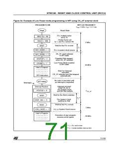
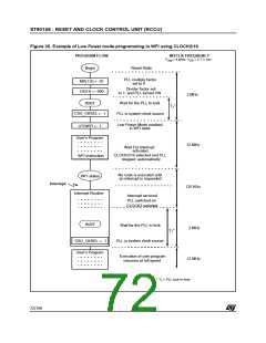
the following paragraphs. Two examples of Low
Power operation in WFI are illustrated in Figure 34
and Figure 35.
It is up to the user program to switch back to a fast-
er clock on the occurrence of an interrupt, taking
care to respect the oscillator and PLL stabilisation
delays, as appropriate.
If low power operation during WFI is disabled
(LPOWFI bit = 0 in the CLKCTL Register), the
CPU CLK is stopped but INTCLK is unchanged.
It should be noted that any of the low power modes
may also be selected explicitly by the user pro-
gram even when not in Wait for Interrupt mode, by
setting the appropriate bits.
If low power operation during Wait for Interrupt is
enabled (LPOWFI bit = 1 in the CLKCTL Register),
as soon as the CPU executes the WFI instruction,
the PLL is turned off and the system clock will be
forced to CLOCK2 divided by 16, or to the external
low frequency clock, CK_AF, if this has been se-
lected by setting WFI_CKSEL, and providing
CKAF_ST is set, thus indicating that the external
clock is selected and actually present on the
CK_AF pin.
6.3.5 Interrupt Generation
System clock selection modifies the CLKCTL and
CLK_FLAG registers.
The clock control unit generates an external inter-
rupt request when CK_AF and CLOCK2/16 are
selected or deselected as system clock source, as
well as when the system clock restarts after a
hardware stop (when the STOP MODE feature is
available on the specific device). This interrupt can
be masked by resetting the INT_SEL bit in the
CLKCTL register. Note that this is the only case in
the ST9 where an an interrupt is generated with a
high to low transition.
If the external clock source is used, the crystal os-
cillator may be stopped by setting the XTSTOP bit,
providing that the CK_AK clock is present and se-
lected, indicated by CKAF_ST being set. The crys-
tal oscillator will be stopped automatically on en-
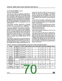
Table 12. Summary of Operating Modes using main Crystal Controlled Oscillator
MODE
INTCLK
CPUCLK DIV2 PRS0-2 CSU_CKSEL MX1-0 DX2-0 LPOWFI XT_DIV16
XTAL/2
x (14/D)
PLL x BY 14
INTCLK/N
INTCLK/N
INTCLK/N
INTCLK/N
1
1
1
1
N-1
N-1
N-1
N-1
1
1
1
1
1 0
0 0
1 1
0 1
D-1
D-1
D-1
D-1
X
X
X
X
1
1
1
1
XTAL/2
x (10/D)
PLL x BY 10
PLL x BY 8
PLL x BY 6
XTAL/2
x (8/D)
XTAL/2
x (6/D)
SLOW 1
SLOW 2
XTAL/2
INTCLK/N
INTCLK/N
1
1
N-1
N-1
X
X
X
X
111
X
X
X
1
0
XTAL/32
WAIT FOR
INTERRUPT
If LPOWFI=0, no changes occur on INTCLK, but CPUCLK is stopped anyway.
LOW POWER
WAIT FOR
INTERRUPT
XTAL/32
XTAL/2
STOP
1
1
X
0
X
0
X
X
1
0
1
1
RESET
INTCLK
00
111
EXAMPLE
XTAL=4.4 MHz
2.2*10/2
= 11MHz
11MHz
1
0
1
00
001
X
1
70/199
9

 ETC [ ETC ]