ST90158 - RESET AND CLOCK CONTROL UNIT (RCCU)
CLOCK MANAGEMENT (Cont’d)
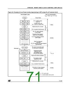
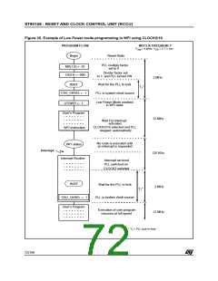
6.3.1 PLL Clock Multiplier Programming
when little processing is being done and the pe-
ripherals are doing most of the work.
The CLOCK1 signal generated by the oscillator
drives a programmable divide-by-two circuit. If the
DIV2 control bit in MODER is set (Reset Condi-
tion), CLOCK2, is equal to CLOCK1 divided by
two; if DIV2 is reset, CLOCK2 is identical to
CLOCK1. Since the input clock to the Clock Multi-
plier circuit requires a 50% duty cycle for correct
PLL operation, the divide by two circuit should be
enabled when a crystal oscillator is used, or when
the external clock generator does not provide a
50% duty cycle. In practice, the divide-by-two is
virtually always used in order to ensure a 50% duty
cycle signal to the PLL multiplier circuit.
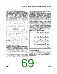
The prescaler divides the input clock by the value
programmed in the control bits PRS2,1,0 in the
MODER register. If the prescaler value is zero, no
prescaling takes place, thus CPUCLK has the
same period and phase as INTCLK. If the value is
different from 0, the prescaling is equal to the val-
ue plus one, ranging thus from two (PRS2,1,0 = 1)
to eight (PRS2,1,0 = 7).
The clock generated is shown in Figure 33, and it
will be noted that the prescaling of the clock does
not preserve the 50% duty cycle, since the high
level is stretched to replace the missing cycles.
When the PLL is active, it multiplies CLOCK2 by 6,
8, 10 or 14, depending on the status of the MX0 -1
bits in PLLCONF. The multiplied clock is then di-
vided by a factor in the range 1 to 7, determined by
the status of the DX0-2 bits; when these bits are
programmed to 111, the PLL is switched off.
This is analogous to the introduction of wait cycles
for access to external memory. When External
Memory Wait or Bus Request events occur, CPU-
CLK is stretched at the high level for the whole pe-
riod required by the function.
Figure 33. CPU Clock Prescaling
Following a RESET phase, programming bits
DX0-2 to a value different from 111 will turn the
PLL on. After allowing a stabilisation period for the
PLL, setting the CSU_CKSEL bit in the
CLK_FLAG Register selects the multiplier clock.
INTCLK
PRS VALUE
000
The maximum frequency allowed for INTCLK is 24
MHz for 5V operation, and 16 MHz for 3V opera-
tion. Care is required, when programming the PLL
multiplier and divider factors, not to exceed the
maximum permissible operating frequency for
INTCLK, according to supply voltage.
001
010
011
CPUCLK
100
The ST9 being a static machine, there is no lower
limit for INTCLK. However, below 1MHz, A/D con-
verter precision (if present) decreases.
101
110
111
6.3.2 CPU Clock Prescaling
The system clock, INTCLK, which may be the out-
put of the PLL clock multiplier, CLOCK2, CLOCK2/
16 or CK_AF, drives a programmable prescaler
which generates the basic time base, CPUCLK,
for the instruction executer of the ST9 CPU core.
This allows the user to slow down program execu-
tion during non processor intensive routines, thus
reducing power dissipation.
VA00260
6.3.3 Peripheral Clock
The system clock, INTCLK, which may be the out-
put of the PLL clock multiplier, CLOCK2, CLOCK2/
16 or CK_AF, is also routed to all ST9 on-chip pe-
ripherals and acts as the central timebase for all
timing functions.
The internal peripherals are not affected by the
CPUCLK prescaler and continue to operate at the
full INTCLK frequency. This is particularly useful
69/199
9

 ETC [ ETC ]