ST90158 - MULTIFUNCTION TIMER (MFT)
MULTIFUNCTION TIMER (Cont’d)
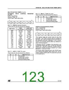
EXTERNAL INPUT CONTROL REGISTER
(T_ICR)
Bits 1:0 = B[0:1]: TxINB Pin event.
These bits are set and cleared by software.
R250 - Read/Write
Register Page: 10
Reset value: 0000 0000 (00h)
B0
B1
TxINB Pin Event
No operation
Falling edge sensitive
Rising edge sensitive
Rising and falling edges
0
0
1
1
0
1
0
1
7
0
IN3
IN2
IN1
IN0
A0
A1
B0
B1
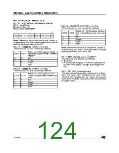
Bits 7:4 = IN[3:0]: Input pin function.
These bits are set and cleared by software.
PRESCALER REGISTER (PRSR)
R251 - Read/Write
Register Page: 10
TxINA
Pin Function
TxINB Input
Pin Function
IN[3:0] bits
Reset value: 0000 0000 (00h)
0000
0001
0010
0011
0100
0101
0110
0111
1000
1001
1010
1011
1100
1101
1110
1111
not used
not used
Gate
Gate
not used
Trigger
not used
Trigger
not used
Trigger
7
0
P7
P6
P5
P4
P3
P2
P1
P0
Ext. Clock
not used
Ext. Clock
Trigger
Clock Down
Ext. Clock
Trigger Down
not used
Autodiscr.
Ext. Clock
Trigger
This register holds the preset value for the 8-bit
prescaler. The PRSR content may be modified at
any time, but it will be loaded into the prescaler at
the following prescaler underflow, or as a conse-
quence of a counter reload (either by software or
upon external request).
Gate
Trigger
Clock Up
Up/Down
Trigger Up
Up/Down
Autodiscr.
Trigger
Following a RESET condition, the prescaler is au-
tomatically loaded with 00h, so that the prescaler
divides by 1 and the maximum counter clock is
generated (OSCIN frequency divided by 6 when
MODER.5 = DIV2 bit is set).
Ext. Clock
Trigger
Gate
The binary value programmed in the PRSR regis-
ter is equal to the divider value minus one. For ex-
ample, loading PRSR with 24 causes the prescal-
er to divide by 25.
Bits 3:2 = A[0:1]: TxINA Pin event.
These bits are set and cleared by software.
A0
A1
TxINA Pin Event
No operation
0
0
1
1
0
1
0
1
Falling edge sensitive
Rising edge sensitive
Rising and falling edges
123/199
9

 ETC [ ETC ]