ST90158 - MULTIFUNCTION TIMER (MFT)
MULTIFUNCTION TIMER (Cont’d)
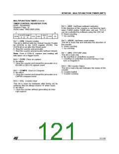
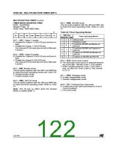
TIMER MODE REGISTER (TMR)
R249 - Read/Write
Register Page: 10
Bit 3 = RM0: REG0R mode.
This bit works together with the BM and RM1 bits
to select the timer operating mode. Refer to Table
24.
Reset value: 0000 0000 (00h)
7
0
Table 24. Timer Operating Modes
TMR Bits
OE1 OE0 BM RM1 RM0 ECK REN C0
Timer Operating Modes
BM RM1 RM0
1
1
x
0
1
Biload mode
Bit 7 = OE1: Output 1 enable.
0: Disable the Output 1 (TxOUTB pin) and force it
high.
1: Enable the Output 1 (TxOUTB pin)
The relevant I/O bit must also be set to Alternate
Function
x
Bicapture mode
Load from REG0R and Monitor on
REG1R
0
0
0
1
0
0
Load from REG0R and Capture on
REG1R
Capture on REG0R and Monitor on
REG1R
0
0
0
1
1
1
Bit 6 = OE0: Output 0 enable.
0: Disable the Output 0 (TxOUTA pin) and force it
high
Capture on REG0R and REG1R
1: Enable the Output 0 (TxOUTA pin).
The relevant I/O bit must also be set to Alternate
Function
Bit 2 = ECK Timer clock control.
0: The prescaler clock source is selected depend-
ing on the IN0 - IN3 bits in the T_ICR register
1: Enter Parallel mode (for Timer 1 and Timer 3
only, no effect for Timer 0 and 2). See Section
9.3.2.12.
Bit 5 = BM: Bivalue mode.
This bit works together with the RM1 and RM0 bits
to select the timer operating mode (see Table 24).
0: Disable bivalue mode
Bit 1 = REN: Retrigger mode.
0: Enable retriggerable mode
1: Disable retriggerable mode
1: Enable bivalue mode
Bit 4 = RM1: REG1R mode.
This bit works together with the BM and RM0 bits
to select the timer operating mode. Refer to Table
24.
Bit 0 = CO: Continous/One shot mode.
0: Continuous mode (with autoreload on End of
Count condition)
Note: This bit has no effect when the Bivalue
Mode is enabled (BM=1).
1: One shot mode
122/199
9

 ETC [ ETC ]