ST90158 - MULTIFUNCTION TIMER (MFT)
MULTIFUNCTION TIMER (Cont’d)
Every software or external trigger event on
REG0R performs a reload from REG0R resetting
the Biload cycle. In One Shot mode (reload initiat-
ed by software or by an external trigger), reloading
is always from REG0R.
By loading the Prescaler Register of Timer 1 with
the value 00h the two timers (Timer 0 and Timer 1)
are driven by the same frequency in parallel mode.
In this mode the clock frequency may be divided
16
by a factor in the range from 1 to 2 .
B) Bicapture Mode
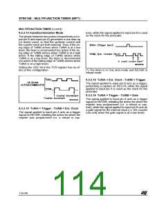
9.3.2.13 Autodiscriminator Mode
The Bicapture Mode is entered by selecting the Bi-
value Mode (the BM bit in TMR is set) and by pro-
gramming REG0R as a capture register (the RM0
bit in TMR is set).
The phase difference sign of two overlapping puls-
es (respectively on TxINB and TxINA) generates a
one step up/down count, so that the up/down con-
trol and the counter clock are both external. The
setting of the UDC bit in the TCR register has no
effect in this configuration.
Every capture event, software simulated (by set-
ting the CP0 flag) or coming directly from the TxI-
NA input line, captures the current counter value
alternately into REG0R and REG1R. When the
BM bit is reset, REG0R is the current register, so
that the first capture, after resetting the BM bit, is
always into REG0R.
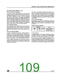
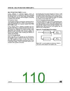
Figure 61. Parallel Mode Description
MFT0
COUNTER
INTCLK/3
PRESCALER 0
9.3.2.12 Parallel Mode
When two MFTs are present on an ST9 device,
the parallel mode is entered when the ECK bit in
the TMR register of Timer 1 is set. The Timer 1
prescaler input is internally connected to the Timer
0 prescaler output. Timer 0 prescaler input is con-
nected to the system clock line.
MFT1
COUNTER
PRESCALER 1
Note: MFT 1 is not available on all devices. Refer to
the device block diagram and register map.
110/199
9

 ETC [ ETC ]