ST72104G, ST72215G, ST72216G, ST72254G
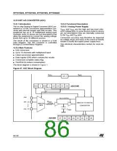
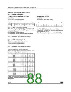
8-BIT A/D CONVERTER (ADC) (Cont’d)
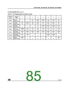
12.5.6 Register Description
CONTROL/STATUS REGISTER (CSR)
Read/Write
DATA REGISTER (DR)
Read Only
Reset Value: 0000 0000 (00h)
Reset Value: 0000 0000 (00h)
7
0
7
0
COCO
0
ADON
0
CH3
CH2
CH1
CH0
D7
D6
D5
D4
D3
D2
D1
D0
Bit 7 = COCO Conversion Complete
This bit is set by hardware. It is cleared by soft-
ware reading the result in the DR register or writing
to the CSR register.
0: Conversion is not complete
1: Conversion can be read from the DR register
Bits 7:0 = D[7:0] Analog Converted Value
This register contains the converted analog value
in the range 00h to FFh.
Note: Reading this register reset the COCO flag.
Bit 6 = Reserved. must always be cleared.
Bit 5 = ADON A/D Converter On
This bit is set and cleared by software.
0: A/D converter is switched off
1: A/D converter is switched on
Bit 4 = Reserved. must always be cleared.
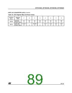
Bits 3:0 = CH[3:0] Channel Selection
These bits are set and cleared by software. They
select the analog input to convert.
Channel Pin*
CH3 CH2 CH1 CH0
AIN0
AIN1
AIN2
AIN3
AIN4
AIN5
AIN6
AIN7
AIN8
0
0
0
0
0
0
0
0
1
1
1
1
1
1
1
1
0
0
0
0
1
1
1
1
0
0
0
0
1
1
1
1
0
0
1
1
0
0
1
1
0
0
1
1
0
0
1
1
0
1
0
1
0
1
0
1
0
1
0
1
0
1
0
1
AIN9
AIN10
AIN11
AIN12
AIN13
AIN14
AIN15
*Note: The number of pins AND the channel selec-
tion varies according to the device. Refer to the de-
vice pinout.
88/140

 ETC [ ETC ]