ST72104G, ST72215G, ST72216G, ST72254G
12.5 8-BIT A/D CONVERTER (ADC)
12.5.1 Introduction
12.5.3 Functional Description
12.5.3.1 Analog Power Supply
The on-chip Analog to Digital Converter (ADC) pe-
ripheral is a 8-bit, successive approximation con-
verter with internal sample and hold circuitry. This
peripheral has up to 16 multiplexed analog input
channels (refer to device pin out description) that
allow the peripheral to convert the analog voltage
levels from up to 16 different sources.
V
and V
are the high and low level refer-
SSA
DDA
ence voltage pins. In some devices (refer to device
pin out description) they are internally connected
to the V and V pins.
DD
SS
Conversion accuracy may therefore be impacted
by voltage drops and noise in the event of heavily
loaded or badly decoupled power supply lines.
The result of the conversion is stored in a 8-bit
Data Register. The A/D converter is controlled
through a Control/Status Register.
See electrical characteristics section for more de-
tails.
12.5.2 Main Features
■ 8-bit conversion
■ Up to 16 channels with multiplexed input
■ Linear successive approximation
■ Data register (DR) which contains the results
■ Conversion complete status flag
■ On/off bit (to reduce consumption)
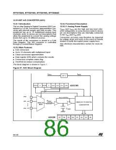
The block diagram is shown in Figure 1.
Figure 47. ADC Block Diagram
f
f
ADC
CPU
DIV 2
COCO
0
ADON
4
0
CH3 CH2 CH1 CH0
ADCCSR
AIN0
AIN1
HOLD CONTROL
R
ADC
ANALOG TO DIGITAL
CONVERTER
ANALOG
MUX
AINx
C
ADC
ADCDR
D7
D6
D5
D4
D3
D2
D1
D0
86/140

 ETC [ ETC ]