ST72104G, ST72215G, ST72216G, ST72254G
INPUT CAPTURE 1 HIGH REGISTER (IC1HR)
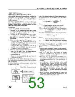
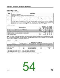
16-BIT TIMER (Cont’d)
STATUS REGISTER (SR)
Read Only
Read Only
Reset Value: Undefined
Reset Value: 0000 0000 (00h)
The three least significant bits are not used.
7
This is an 8-bit read only register that contains the
high part of the counter value (transferred by the
input capture 1 event).
0
0
ICF1 OCF1 TOF ICF2 OCF2
0
0
7
0
MSB
LSB
Bit 7 = ICF1 Input Capture Flag 1.
0: No input capture (reset value).
1: An input capture has occurred on the ICAP1 pin
or the counter has reached the OC2R value in
PWM mode. To clear this bit, first read the SR
register, then read or write the low byte of the
IC1R (IC1LR) register.
INPUT CAPTURE 1 LOW REGISTER (IC1LR)
Read Only
Reset Value: Undefined
This is an 8-bit read only register that contains the
low part of the counter value (transferred by the in-
put capture 1 event).
Bit 6 = OCF1 Output Compare Flag 1.
0: No match (reset value).
1: The content of the free running counter matches
the content of the OC1R register. To clear this
bit, first read the SR register, then read or write
the low byte of the OC1R (OC1LR) register.
7
0
MSB
LSB
Bit 5 = TOF Timer Overflow Flag.
0: No timer overflow (reset value).
1: The free running counter has rolled over from
FFFFh to 0000h. To clear this bit, first read the
SR register, then read or write the low byte of
the CR (CLR) register.
OUTPUT COMPARE
(OC1HR)
1
HIGH REGISTER
Read/Write
Reset Value: 1000 0000 (80h)
This is an 8-bit register that contains the high part
of the value to be compared to the CHR register.
Note: Reading or writing the ACLR register does
not clear TOF.
7
0
MSB
LSB
Bit 4 = ICF2 Input Capture Flag 2.
0: No input capture (reset value).
1: An input capture has occurred on the ICAP2
pin. To clear this bit, first read the SR register,
then read or write the low byte of the IC2R
(IC2LR) register.
OUTPUT COMPARE
(OC1LR)
1
LOW REGISTER
Read/Write
Reset Value: 0000 0000 (00h)
Bit 3 = OCF2 Output Compare Flag 2.
0: No match (reset value).
This is an 8-bit register that contains the low part of
the value to be compared to the CLR register.
1: The content of the free running counter matches
the content of the OC2R register. To clear this
bit, first read the SR register, then read or write
the low byte of the OC2R (OC2LR) register.
7
0
MSB
LSB
Bit 2-0 = Reserved, forced by hardware to 0.
57/140

 ETC [ ETC ]