ST6200C/ST6201C/ST6203C
WATCHDOG TIMER (Cont’d)
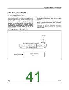
9.1.3 Functional Description
When STOP mode is not required, hardware acti-
vation without EXTERNAL STOP MODE CON-
TROL should be preferred, as it provides maxi-
mum security, especially during power-on.
The watchdog activation is selected through an
option in the option bytes:
– HARDWARE watchdog option
When STOP mode is required, hardware activa-
tion and EXTERNAL STOP MODE CONTROL
should be chosen. NMI should be high by default,
to allow STOP mode to be entered when the MCU
is idle.
After reset, the watchdog is permanently active,
the C bit in the WDGR is forced high and the user
can not change it. However, this bit can be read
equally as 0 or 1.
– SOFTWARE watchdog option
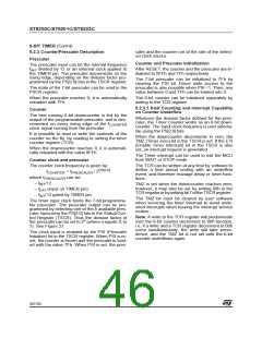
The NMI pin can be connected to an I/O line (see
Figure 26) to allow its state to be controlled by soft-
ware. The I/O line can then be used to keep NMI
low while Watchdog protection is required, or to
avoid noise or key bounce. When no more
processing is required, the I/O line is released and
the device placed in STOP mode for lowest power
consumption.
After reset, the watchdog is deactivated. The func-
tion is activated by setting C bit in the WDGR reg-
ister. Once activated, it cannot be deactivated.
The counter value stored in the WDGR register
(bits SR:T0), is decremented every 3072 clock cy-
cles. The length of the timeout period can be pro-
grammed by the user in 64 steps of 3072 clock cy-
cles.
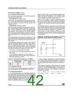
Figure 26. A typical circuit making use of the
EXERNAL STOP MODE CONTROL feature
If the watchdog is activated (by setting the C bit)
and when the SR bit is cleared, the watchdog initi-
ates a reset cycle pulling the reset pin low for typi-
cally 500ns.
The application program must write in the WDGR
register at regular intervals during normal opera-
tion to prevent an MCU reset. The value to be
stored in the WDGR register must be between
FEh and 02h (see Table 12). To run the watchdog
function the following conditions must be true:
SWITCH
NMI
I/O
– The C bit is set (watchdog activated)
– The SR bit is set to prevent generating an imme-
diate reset
– The T[5:0] bits contain the number of decre-
ments which represent the time delay before the
watchdog produces a reset.
VR02002
Table 12. Watchdog Timing (f
= 8 MHz)
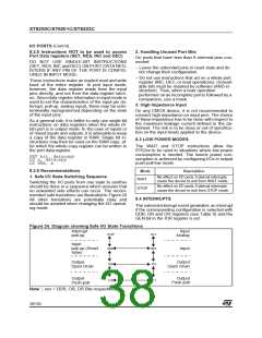
2. When software activation is selected (WDACT
bit in Option byte) and the Watchdog is not activat-
ed, the downcounter may be used as a simple 7-
bit timer (remember that the bits are in reverse or-
der).
OSC
WDGR Register
initial value
WDG timeout period
(ms)
Max.
Min.
FEh
02h
24.576
0.384
The software activation option should be chosen
only when the Watchdog counter is to be used as
a timer. To ensure the Watchdog has not been un-
expectedly activated, the following instructions
should be executed:
9.1.3.1 Software Reset
The SR bit can be used to generate a software re-
set by clearing the SR bit while the C bit is set.
9.1.4 Recommendations
jrr 0, WDGR, #+3 ; If C=0,jump to next
ldi WDGR, 0FDH ; SR=0 -> reset
1. The Watchdog plays an important supporting
role in the high noise immunity of ST62xx devices,
and should be used wherever possible. Watchdog
related options should be selected on the basis of
a trade-off between application security and STOP
mode availability (refer to the description of the
WDACT and EXTCNTL bits on the Option Bytes).
next :
42/104
1

 ETC [ ETC ]