RTL8211C & RTL8211CL
Datasheet
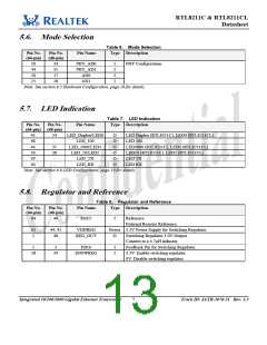
5.6. Mode Selection
Table 6. Mode Selection
Pin No.
(64-pin)
Pin No.
(48-pin)
Pin Name
Type Description
50
44
20
21
34
35
17
18
PHY_AD0
PHY_AD1
AN0
I
I
I
I
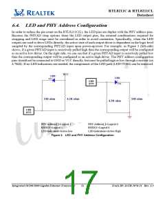
PHY Configuration.
AN1
Note: See section 6.3 Hardware Configuration, page 10 for details.
5.7. LED Indication
Table 7. LED Indication
Type Description
Pin No.
Pin No.
Pin Name
(64-pin) (48-pin)
43
48
44
50
39
40
34
-
LED_Duplex/LED0
LED_100
O
O
O
O
O
O
LED Duplex (RTL8211C), LED0 (RTL8211CL)
LED 100
35
38
-
LED_1000/LED1
LED_10/LED2
LED_TX
LED1000 (RTL8211C), LED1 (RTL8211CL)
LED10 (RTL8211C), LED2 (RTL8211CL)
LED TX
LED RX
-
LED_RX
Note: See section 6.8 LED Configuration, page 19 for details.
5.8. Regulator and Reference
Table 8. Regulator and Reference
Type Description
Pin No.
(64-pin)
Pin No.
(48-pin)
Pin Name
64
46
RSET
I
Reference.
External Resistor Reference.
63
1
44, 45
48
VDDREG
REG_OUT
Power 3.3V Power Supply for Switching Regulator.
O
Switching Regulator 1.0V Output.
Connect to a 4.7µH inductor.
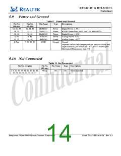
5
3
FB10
I
I
Feedback Pin for Switching Regulator.
3.3V: Enable switching regulator.
0V: Disable switching regulator.
58
39
ENSWREG
Integrated 10/100/1000 Gigabit Ethernet Transceiver
7
Track ID: JATR-1076-21 Rev. 1.3

 ETC [ ETC ]