RTL8211C & RTL8211CL
Datasheet
5. Pin Descriptions
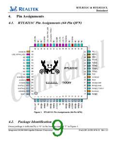
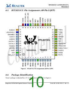
Note that some pins have multiple functions. Refer to the Pin Assignment figures on page 3 (RTL8211C)
and on page 4 (RTL8211CL) for a graphical representation.
5.1. Transceiver Interface
Table 1. Transceiver Interface
Pin No.
(64-pin)
Pin No.
(48-pin)
Pin Name
MDI[0]+
MDI[0]−
MDI[1]+
MDI[1]−
Type Description
3
4
6
7
1
2
4
5
IO
IO
IO
IO
In MDI mode, this is the first pair in 1000Base-T, i.e., the BI_DA+/- pair,
and is the transmit pair in 10Base-T and 100Base-TX.
In MDI crossover mode, this pair acts as the BI_DB+/- pair, and is the
receive pair in 10Base-T and 100Base-TX.
In MDI mode, this is the second pair in 1000Base-T, i.e., the BI_DB+/-
pair, and is the receive pair in 10Base-T and 100Base-TX.
In MDI crossover mode, this pair acts as the BI_DA+/- pair, and is the
transmit pair in 10Base-T and 100Base-TX.
11
12
14
15
8
9
MDI[2]+
MDI[2]−
MDI[3]+
MDI[3]−
IO
IO
IO
IO
In MDI mode, this is the third pair in 1000Base-T, i.e., the BI_DC+/- pair.
In MDI crossover mode, this pair acts as the BI_DD+/- pair.
11
12
In MDI mode, this is the fourth pair in 1000Base-T, i.e., the BI_DD+/-
pair.
In MDI crossover mode, this pair acts as the BI_DC+/- pair.
5.2. Clock
Table 2. Clock
Pin No.
Pin No.
Pin Name
Type Description
(64-pin) (48-pin)
61
62
41
42
43
32
CKXTAL1
CKXTAL2
CLK125
I
Input/Output of 25MHz Clock Reference.
125MHz Reference Clock Generated from Internal PLL.
O
O
Integrated 10/100/1000 Gigabit Ethernet Transceiver
5
Track ID: JATR-1076-21 Rev. 1.3

 ETC [ ETC ]