RTL8211C & RTL8211CL
Datasheet
6.4. LED and PHY Address Configuration
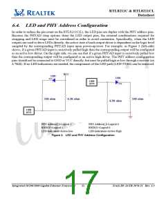
In order to reduce the pin count on the RTL8211C(L), the LED pins are duplex with the PHY address pins.
Because the PHYAD strap options share the LED output pins, the external combinations required for
strapping and LED usage must be considered in order to avoid contention. Specifically, when the LED
outputs are used to drive LEDs directly, the active state of each output driver is dependent on the logic level
sampled by the corresponding PHYAD input upon power-up/reset. For example, as Figure 3 (left-side)
shows, if a given PHYAD input is resistively pulled high then the corresponding output will be configured
as an active low driver. On the right side, we can see that if a given PHYAD input is resistively pulled low
then the corresponding output will be configured as an active high driver. The PHY address configuration
pins should not be connected to GND or VCC directly, but must be pulled high or low through a resistor (ex
4.7KΩ). If no LED indications are needed, the components of the LED path (LED+510Ω) can be removed.
PHY Address[:]=Logical 1
RXDLY=Logical 1
PHY Address[:]=Logical 0
RXDLY=Logical 0
LED Indication=Active low
LED Indication=Active High
Figure 3. LED and PHY Address Configuration
Integrated 10/100/1000 Gigabit Ethernet Transceiver
11
Track ID: JATR-1076-21 Rev. 1.3

 ETC [ ETC ]