RDA Microelectronics, Inc.
RDA5807SP FM Tuner V1.0
5
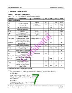
Receiver Characteristics
Table 5-1
Receiver Characteristics
(VDD = 2.7 to 5.5 V, TA = -25 to 85 °C, unless otherwise specified)
SYMBOL
PARAMETER
CONDITIONS
MIN
TYP
MAX
UNIT
General specifications
BAND=0
BAND=1
87
76
108
91
2
MHz
MHz
mV EMF
W
FM Input Frequency
Fin
Sensitivity1,2,3
LNA Input Resistance 7
LNA Input Capacitance 7
Input IP34
(S+N)/N=26dB
1.5
150
4
Vrf
Rin
2
6
-
pF
Cin
AGCD=1
m=0.3
80
40
45
IP3in
αam
S200
dBmV
dB
AM Suppression1,2
-
-
Adjacent Channel Selectivity
Left and Right Audio
Frequency Output Voltage
(Pins LOUT and ROUT)
Maximum Signal Plus Noise
to Noise Ratio1,2,3,5
-
dB
±200KHz
Volume_dac[3:0] =1111
110
mV
VAFL; VAFR
54
35
60
-
-
-
dB
dB
%
(S+N)/N
αSCS
THD
αAOI
Stereo Channel Separation
Audio Total Harmonic
Distortion1,3,6
0.3
0.5
1
Audio Output L/R Imbalance
Audio Output Loading
Resistance
dB
W
Single-ended
32
-
-
RL
Pins LNAN, LNAP, LOUT, ROUT and NC(22,23)
Pins LNAN and LNAP Input
Vcom_rfin
Float
1.25
0.5
V
V
V
Common Mode Voltage
Audio Output Common
1.2
1.3
Vcom
Mode Voltage8
Pins NC (22, 23) Common
0.45
0.55
Vcom_nc
Mode Voltage
! The NC(22, 23) pins SHOULD BE left floating.
Notes:
1. Fin=76 to 108MHz; Fmod=1KHz; de-emphasis=75ms; MONO=1; L=R unless noted otherwise;
2. Df=22.5KHz;
3. BAF = 300Hz to 15KHz, RBW <=10Hz;
4. |f2-f1|>1MHz, f0=2xf1-f2, AGC disable, Fin=76 to 108MHz;
5. PRF=60dBUV;
6. Df=75KHz.
7. Measured at VEMF = 1 m V, f RF = 76 to 108MHz
8. At LOUT and ROUT pins
The information contained herein is the exclusive property of RDA and shall not be distributed, reproduced, or disclosed in whole or in
part without prior written permission of RDA.
Page 6 of 21

 ETC [ ETC ]