®
PMD-100
PMD-100 Process Decoder
Timing Characteristics
The PMD-100 is designed as a synchronous circuit, which means that it uses a master clock input XTI which is always
synchronized with and typically derived from the input data stream. The master clock frequency can be either 256 or 384
times the input sampling frequency (256 Fs or 384 Fs). If XTIM is low (XTI = 256 Fs), XTI must be between 8.192 and
14.1312 MHz with a 33 to 67% duty cycle. If XTIM is high (XTI = 384 Fs), XTI must be between 12.288 and 18.432
MHz with a 33 to 67% duty cycle, or between 18.432 and 21.1968 MHz with a 40 to 60% duty cycle. A selection of
timing values are as follows:
The PMD-100 constantly provides WCKO and BCKO outputs even if input data (DIN) and/or master clock (XTI) is lost.
This constant clock output eliminates the possiblility of spikes or DC offsets at the DAC’s output. It is recommended that
if DIN or XTI are lost, hard mute (HMUTE) is enabled to prevent invalid data output. If the chip detects a synchronization
error between the master clock (XTI) and the input word clock (LRCI) it automatically exerts a hard mute internally.
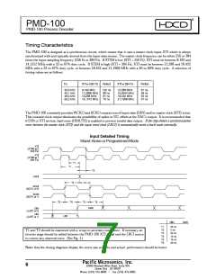
Input Detailed Timing
Stand-Alone or Programmed Mode
T1 and T2 should be examined with a ‘scope to ascertain compliance. If necessary, an
inverter stage should be added between the PMD-100 XTI signal and the LRCI source
to correct any observed error. (See Fig. 1.)
Note: that the timing diagrams display the worst case scenario and actual performance should be better.
Pacific Microsonics, Inc.
6
32990 Alvarado Niles Road, Suite 910
Union City , CA 94587
Phone (510) 475-8000
Fax (510) 475-8005

 ETC [ ETC ]