®
PMD-100
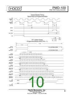
PMD-100 Process Decoder
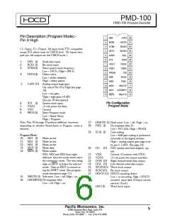
Pin Description (Program Mode) -
Pin 9 High
( I = Input, O = Output. All input levels TTL compatible
except XTI which must be CMOS level. No inputs have
pull-ups. All outputs are full CMOS levels. )
1:
2:
3:
DIN (I)
BCKI (I)
XTIM (I)
Serial data input.
Bit clock input.
Select system clock frequency.
Low = 256 Fs, High = 384 Fs.
Dither select.
4:
DITH (I)
Low = dither disabled,
High = dither added.
5:
GAIN (O) Analog output stage gain.
Use only if Pin 19 is High (see page
14).
Low = low gain,
High = high gain (+6 dB).
(See pin 19 description).
System clock input.
+5 volt power for filter.
Ground
Select Program mode.
Low = Stand-Alone,
High = Program.
6:
7:
8:
9:
XTI (I)
VDD1
VSS1
PROG(I)
Note: Pins 10 through 14 perform different functions
depending on whether Stand-Alone or Program mode is
selected.
17: HMUTE (I) Hard mute. Low = off, High = on.
18: FSEL (I)
De-emphasis filter Fs.
Low = 44.1 kHz, High = 48 kHz.
Gain scaling.
19: SCAL (I)
Program Mode:
Low = 6dB gain scaling is performed
internally in the digital domain,
High = analog output gain stage is set
by pin 5 GAIN. (See page 14).
10: MS1 (I)
11: MS2 (I)
12: MS3 (I)
13: MDT (I)
14: MEN (I)
Mode set bit.
Mode set bit.
Mode set bit.
Mode data.
20: DG (O) DAC sample and hold deglitch sig
nal.
Mode enable.
MS1, MS2 and MS3 form eight
different three bit words which select
the command mode. The next rising
edge on MEN activates the selected
mode. Data on MDT is entered us
ing the SHIFT mode (See program
mode description page 11.)
21: VSS2
22: VDD2
Ground. (Common with VSS1)
+5 volt power for output interface.
23: DOR (O) Right channel serial data output.
24: DOL (O) Left channel serial data output.
25: WCKO(O) Word clock output.
26: BCKO(O) Bit clock output.
27: HDCD (O) HDCD encoding detect.
Low = no encoding. High = HDCD
15: SMUTE (I) Soft mute. Low = off, High = on.
16: DEEMPH(I) De-emphasis filter.
Low = off, High = on.
encoded input data. (Output current
rated at 12mA.)
28: LRCI (I)
Word clock input.
Pacific Microsonics, Inc.
32990 Alvarado Niles Road, Suite 910
Union City, CA 94587
5
Phone (510) 475-8000
Fax (510) 475-8005

 ETC [ ETC ]