®
PMD-100
PMD-100 Process Decoder
Mode Control
DGH0, DGH1, DGH2, DGH3, DGH4:
The rising edge of DG can be programmed to oc-
cur at any one of 32 deglitch intervals dividing the
output sampling period. This five bit word selects
the rising edge of the deglitch interval. (In Stand-
Alone Mode, DG goes high at the beginning of the
31st interval).
The 24-bit mode control flag entered on pin 13 MDT has
the names and functions listed below: (Data is entered in
the order listed. Multiple bit fields, such as OVER are en-
tered LSB first (OVER0). Refer to the Mode Control Reg-
ister diagram.
OVER0, OVER1:
LRPL:
00
10
01
11
(Not used)
0
1
LRCI rising edge is the start edge.*
LRCI falling edge is the start edge.
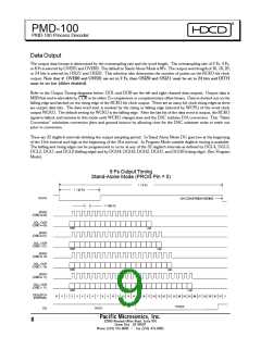
Output data oversampling rate is 2 Fs.
Output data oversampling rate is 4 Fs.
Output data oversampling rate is 8 Fs.*
OSIZ0, OSIZ1:
00
10
01
11
Output word length is 16 bits.
BCPL:
JUST:
Output word length is 18 bits.
Output word length is 20 bits.
Output word length is 24 bits.
0
1
Input data is latched on BCKI rising edge.
Input data is latched on BCKI falling edge.
DITH0, DITH1, DITH2:
000 Dither mode 0.
0
1
Input data is left justified up to 24 bits.
Input data is right justified, assumed to be
16 bits.
Minimum high frequency weighted*
100 Dither mode 1.
010 Dither mode 2.
110 Dither mode 3.
001 Dither mode 4.
101 Dither mode 5.
011 Dither mode 6.
WCPL:
0
1
Output word boundry is on WCKO falling edge.*
Output word boundry is on WCKO rising edge.
COB:
0
1
2’s complement output data.
Complementary offset binary output data.
Maximum high frequency weighted.
111 Dither mode 7.
DGL0, DGL1, DGL2, DGL3, DGL4:
The falling edge of DG can be programmed to occur
at the beginning of any one of 32 deglitch intervals
dividing the output sampling period. This five bit
word selects the falling edge of the deglitch interval.
(In Stand-Alone Mode, DG goes low at the begin-
ning of the 15th interval).
Minimum white triangular PDF dither.
RESA:
RESB:
0
0
Reserved, must be set to 0.
Reserved, must be set to 0.
RESB is the last bit entered.
*Denotes default value in Stand-Alone Mode.
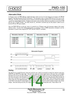
Mode Control Register
Pacific Microsonics, Inc.
32990 Alvarado Niles Road, Suite 910
Union City , CA 94587
12
Phone (510) 475-8000
Fax (510) 475-8005

 ETC [ ETC ]