®
PMD-100
PMD-100 Process Decoder
Dither Modes
The PMD-100 provides 8 different output dithers in Program mode. All dither levels are available for output data
widths from 16 to 24 bits at 8 Fs and 4 Fs oversampling rates only. Dither must be disabled if the 2 Fs oversampling rate
is selected (as well as 24 bit mode must be selected when the 2 Fs oversampling rate is selected). There are seven levels
of high-frequency weighted dither (modes 0-6) plus minimum amplitude white triangular PDF dither (mode 7). Modes
0 and 7 are minimum amplitude dithers which correct quantizing errors only, whereas modes 1 through 6 are increasing
levels of high-frequency weighted dither designed to smooth out non-linearity errors in multi-bit DAC’s (Modes 0 or 7
are appropriate for single-bit DAC’s). The HF weighted dithers put the dither energy above the audio spectrum, where
most of it is later filtered out by the analog low-pass filter following the DAC. In general, multi-bit DAC’s behave better
with high levels of dither, but some analog circuits following the DAC may have problems with transient intermodulation
distortion (TIM) when confronted with high levels of high frequency energy. The best dither level for a particular circuit
implementation must be determined empirically.
Dither Notes:
1) Dither level 6 is the highest level of high-frequency weighted dither available with the PMD-100.
2) In Stand-Alone Mode, dither mode 0 (minimum high frequency weighted) is available. Setting pin 4 DITH low
will disable all dither including programmed dither and should be used only for test purposes.
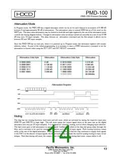
Gain and Scale
The PMD-100 has a design attenuation of 1 dB to allow for filter overshoot on transients.
Most HDCD recordings are encoded using peak extension which gives them more “head room” than standard 16 bit
recordings. In order to ensure that the average program output level of most HDCD recordings match that of standard
recordings, it is necessary to increase the gain of the system 6 dB for those HDCD recordings, or, equivalently, reduce the
gain of standard recordings 6 dB. This can be done either in the analog domain after the DAC’s, which allows the full range
of the DAC’s to be used for both types of recordings, or in the digital domain within the PMD-100.
Note that one or the other of these gain scaling options must be used.
If the designer elects to use the analog approach, a 6 dB glitch-free gain change, controlled by the GAIN output of the chip,
must be provided in the analog circuit. In this case, the SCAL pin is tied high. Since HDCD recordings can have peaks
which are 6 dB higher than standard recordings with the same average levels, the analog circuits must provide enough head
room for these higher levels. The gain change switching in the analog circuitry should occur within 50 msec of the GAIN
output change to insure proper audio output levels.
To elect the digital scaling option, the SCAL pin is tied low and the GAIN pin must be left open. In this case, standard 16
bit recordings and those HDCD recordings encoded without peak extension are attenuated 6 dB inside the chip. The
digital implementation has the advantage of simplicity and the lack of audible glitches, but does not use 1 bit of DAC
resolution on non-HDCD recordings. If 20 bit DAC’s are used, especially in conjunction with the PMD-100’s output
dither options, this does not represent much of a loss in practice since standard recordings only have 16 bit resolution.
However, if 20 or 24-bit signal sources are expected, gain scaling is best accomplished in the analog domain.
De-emphasisFilter
The purpose of the digital de-emphasis filter is to reduce high-frequency quantization noise and to increase dynamic
range with pre-emphasized non-HDCD encoded recordings. De-emphasis is turned ON by setting the DEEMPH
input HIGH. The filter coefficients are selected for the input data sample frequency (44.1 or 48 kHz) by setting the
FSEL mode control flag.
Pacific Microsonics, Inc.
14
32990 Alvarado Niles Road, Suite 910
Union City , CA 94587
Phone (510) 475-8000
Fax (510) 475-8005

 ETC [ ETC ]