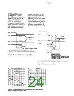
To minimize dead time in a given
design, the turn on of LED2
should be delayed (relative to the
turn off of LED1) so that under
worst-case conditions, transistor
Q1 has just turned off when
Delaying the LED signal by the
maximum propagation delay
difference ensures that the
minimum dead time is zero, but it
does not tell a designer what the
maximum dead time will be. The
maximum dead time is equivalent
Note that the propagation delays
used to calculate PDD and dead
time are taken at equal tempera-
tures and test conditions since
the optocouplers under consider-
ation are typically mounted in
close proximity to each other and
are switching identical IGBTs.
transistor Q2 turns on, as shown
in Figure 35. The amount of delay to the difference between the
necessary to achieve this condi-
tions is equal to the maximum
value of the propagation delay
difference specification, PDDMAX
which is specified to be 350 ns
over the operating temperature
range of -40°C to 100°C.
maximum and minimum propaga-
tion delay difference specifica-
tions as shown in Figure 36. The
maximum dead time for the
HCPL-3120 is 700 ns (= 350 ns -
(-350 ns)) over an operating
temperature range of -40°C to
100°C.
,
For technical assistance or the location of
your nearest Hewlett-Packard sales office,
distributor or representative call:
Americas/Canada: 1-800-235-0312 or
408-654-8675
Far East/Australasia: Call your local HP
sales office.
Japan: (81 3) 3335-8152
Europe: Call your local HP sales office.
Data subject to change.
Copyright © 1997 Hewlett-Packard Co.
Obsoletes 5965-4779E
Printed in U.S.A.
5965-7875E (7/97)

 ETC [ ETC ]