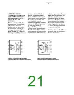
21
CMR with the LED On
(CMRH).
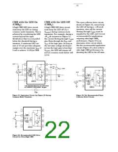
A high CMR LED drive circuit
must keep the LED on during
common mode transients. This is
achieved by overdriving the LED
current beyond the input
threshold so that it is not pulled
below the threshold during a
transient. A minimum LED cur-
rent of 10 mA provides adequate
margin over the maximum IFLH of
5 mA to achieve 15 kV/µs CMR.
CMR with the LED Off
(CMRL).
The open collector drive circuit,
shown in Figure 32, cannot keep
the LED off during a +dVcm/dt
transient, since all the current
flowing through CLEDN must be
supplied by the LED, and it is not
recommended for applications
requiring ultra high CMRL
performance. Figure 33 is an
alternative drive circuit which,
like the recommended application
circuit (Figure 25), does achieve
ultra high CMR performance by
shunting the LED in the off state.
A high CMR LED drive circuit
must keep the LED off (VF ≤
VF(OFF)) during common mode
transients. For example, during a
-dVcm/dt transient in Figure 31,
the current flowing through CLEDP
also flows through the RSAT and
VSAT of the logic gate. As long as
the low state voltage developed
across the logic gate is less than
VF(OFF), the LED will remain off
and no common mode failure will
occur.
+5 V
1
8
0.1
µF
+
–
C
LEDP
V
= 18 V
CC
2
7
6
5
+
1
2
3
4
8
7
6
5
I
LEDP
V
SAT
+5 V
–
C
LEDP
3
4
• • •
• • •
C
LEDN
Rg
SHIELD
C
I
LEDN
Q1
LEDN
* THE ARROWS INDICATE THE DIRECTION
OF CURRENT FLOW DURING –dV /dt.
SHIELD
CM
+
–
V
CM
Figure 31. Equivalent Circuit for Figure 25 During
Common Mode Transient.
Figure 32. Not Recommended Open
Collector Drive Circuit.
1
2
3
4
8
7
6
5
+5 V
C
C
LEDP
LEDN
SHIELD
Figure 33. Recommended LED Drive
Circuit for Ultra-High CMR.

 ETC [ ETC ]