19
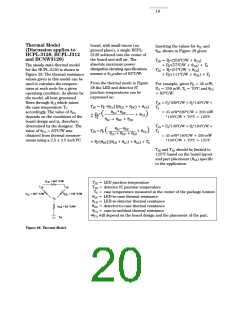
Thermal Model
board, with small traces (no
ground plane), a single HCPL-
3120 soldered into the center of
the board and still air. The
absolute maximum power
dissipation derating specifications
assume a θCAvalue of 83°C/W.
Inserting the values for θLC and
θDC shown in Figure 28 gives:
(Discussion applies to
HCPL-3120, HCPL-J312
and HCNW3120)
•
TJE = P (256°C/W + θCA)
E
•
The steady state thermal model
for the HCPL-3120 is shown in
Figure 28. The thermal resistance
values given in this model can be
used to calculate the tempera-
tures at each node for a given
operating condition. As shown by
the model, all heat generated
flows through θCA which raises
the case temperature TC
accordingly. The value of θCA
depends on the conditions of the
board design and is, therefore,
determined by the designer. The
value of θCA = 83°C/W was
+ PD (57°C/W + θCA) + TA
•
TJD = P (57°C/W + θCA)
E
•
+ PD (111°C/W + θCA) + TA
From the thermal mode in Figure
28 the LED and detector IC
junction temperatures can be
expressed as:
For example, given PE = 45 mW,
PO = 250 mW, TA = 70°C and θCA
= 83°C/W:
•
•
TJE = PE 339°C/W + PD 140°C/W +
•
TJE = P (θLC||(θLD + θDC) + θCA)
E
T
A
θLC * θDC
= 45 mW• 339°C/W + 250 mW
• 140°C/W + 70°C = 120°C
•
+ P
+ TAD
(
–––––––––––––––– + θCA)
θLC + θDC + θLD
•
•
TJD = PE 140°C/W + PD 194°C/W +
•
θ
θDC
TJD = PE
(
–––––L–C––––––––– + θCA
)
T
A
θLC + θDC + θLD
obtained from thermal measure-
ments using a 2.5 x 2.5 inch PC
= 45 mW• 140C/W + 250 mW
• 194°C/W + 70°C = 125°C
•
+ PD (θDC||(θLD + θLC) + θCA) + TA
TJE and TJD should be limited to
125°C based on the board layout
and part placement (θCA) specific
to the application.
θ
= 442 °C/W
LD
TJE = LED junction temperature
TJD = detector IC junction temperature
T
T
JD
JE
TC = case temperature measured at the center of the package bottom
θLC = LED-to-case thermal resistance
θ
= 467 °C/W
θ
= 126 °C/W
DC
LC
T
C
θLD = LED-to-detector thermal resistance
θDC = detector-to-case thermal resistance
θ
= 83 °C/W*
CA
θCA = case-to-ambient thermal resistance
θCA will depend on the board design and the placement of the part.
T
A
Figure 28. Thermal Model.

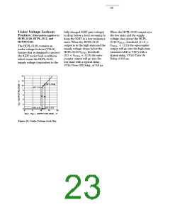
 ETC [ ETC ]